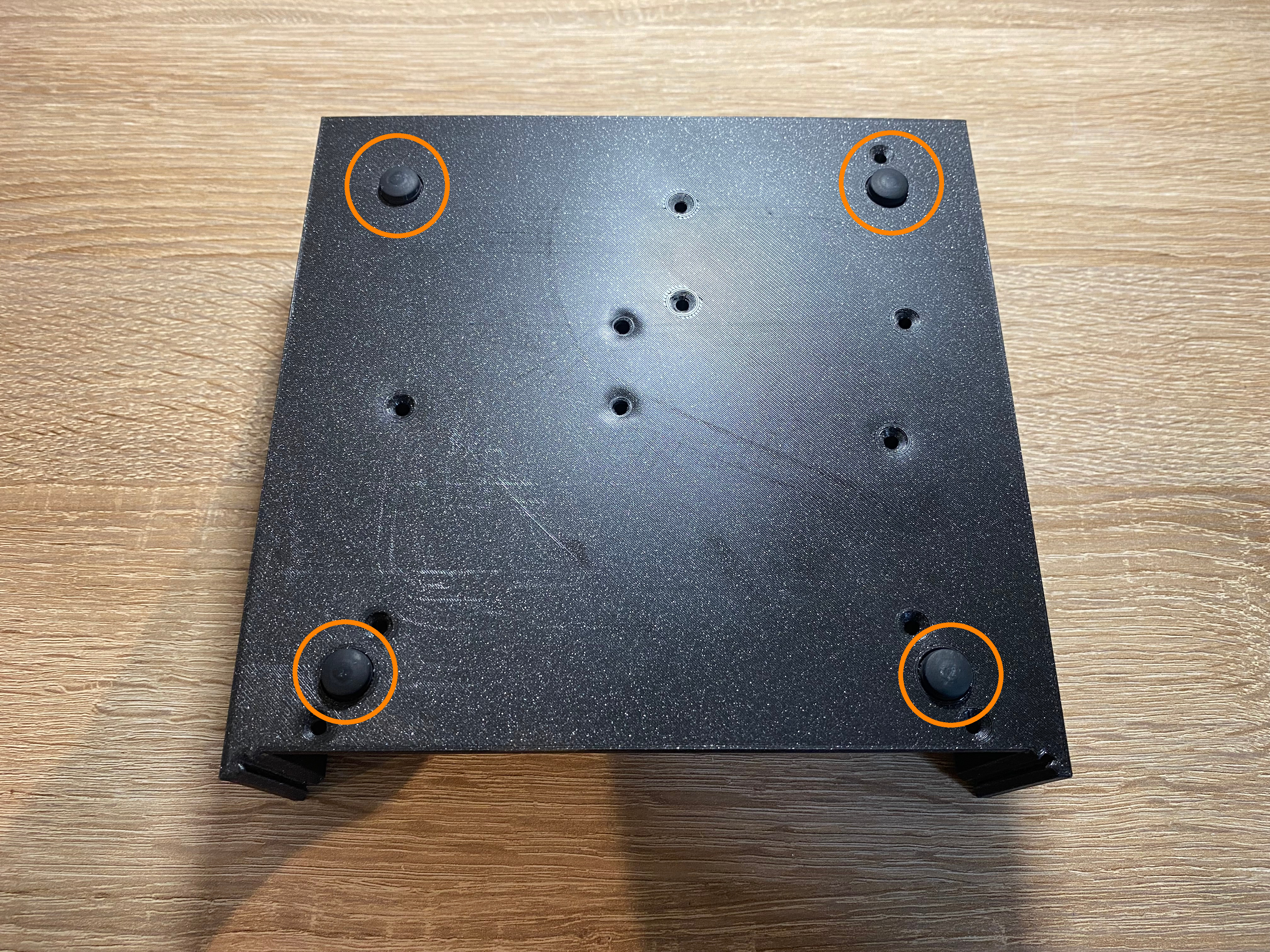
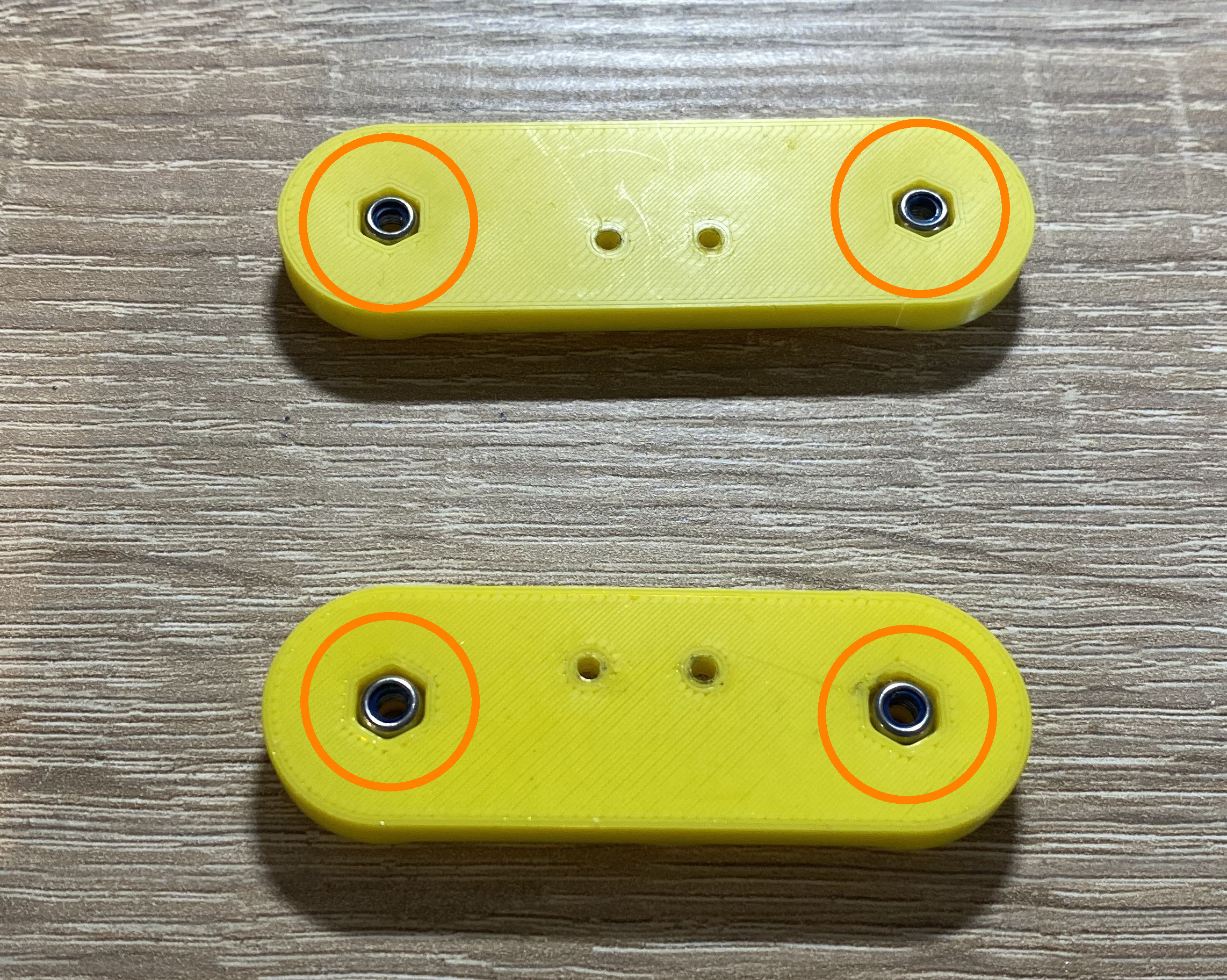
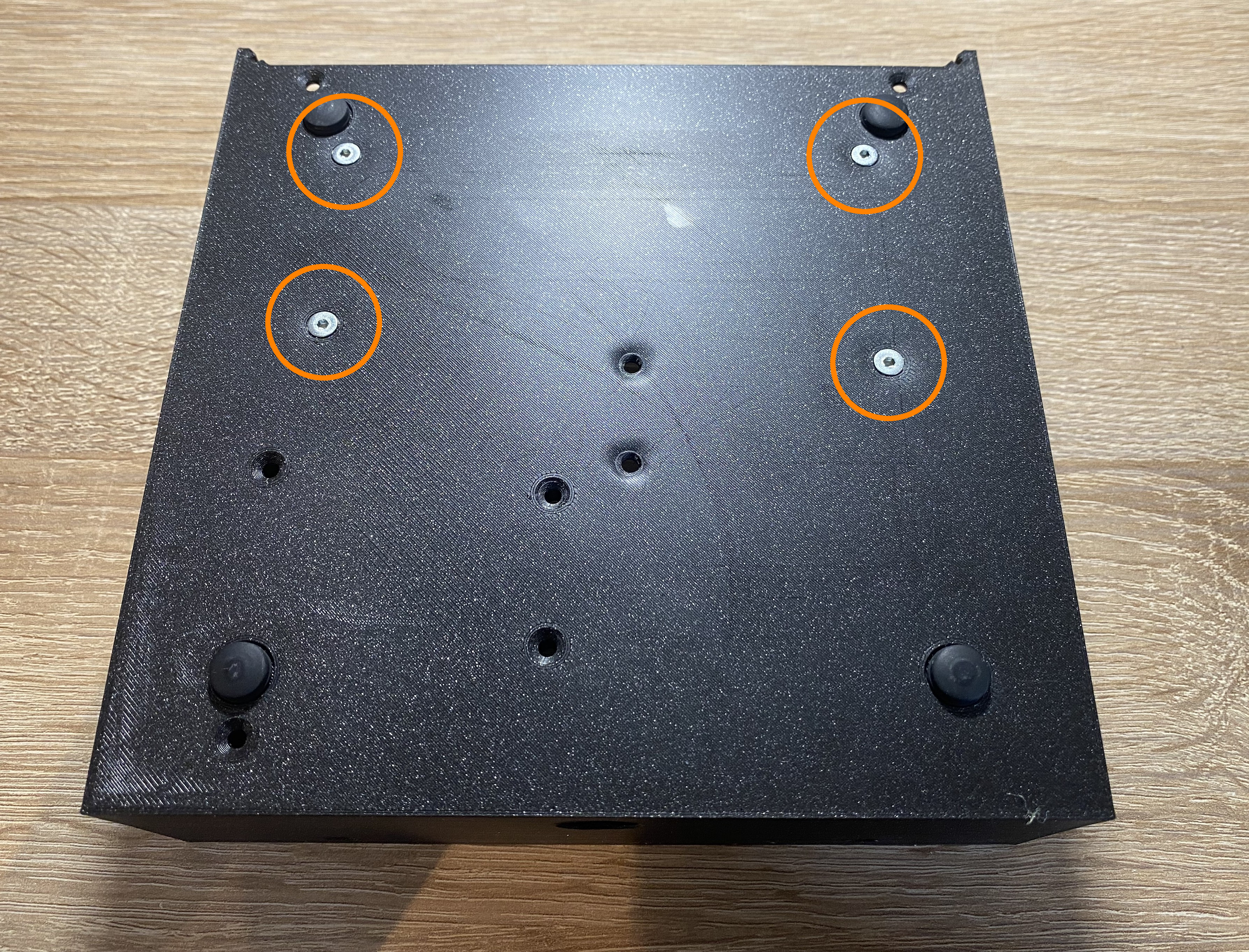
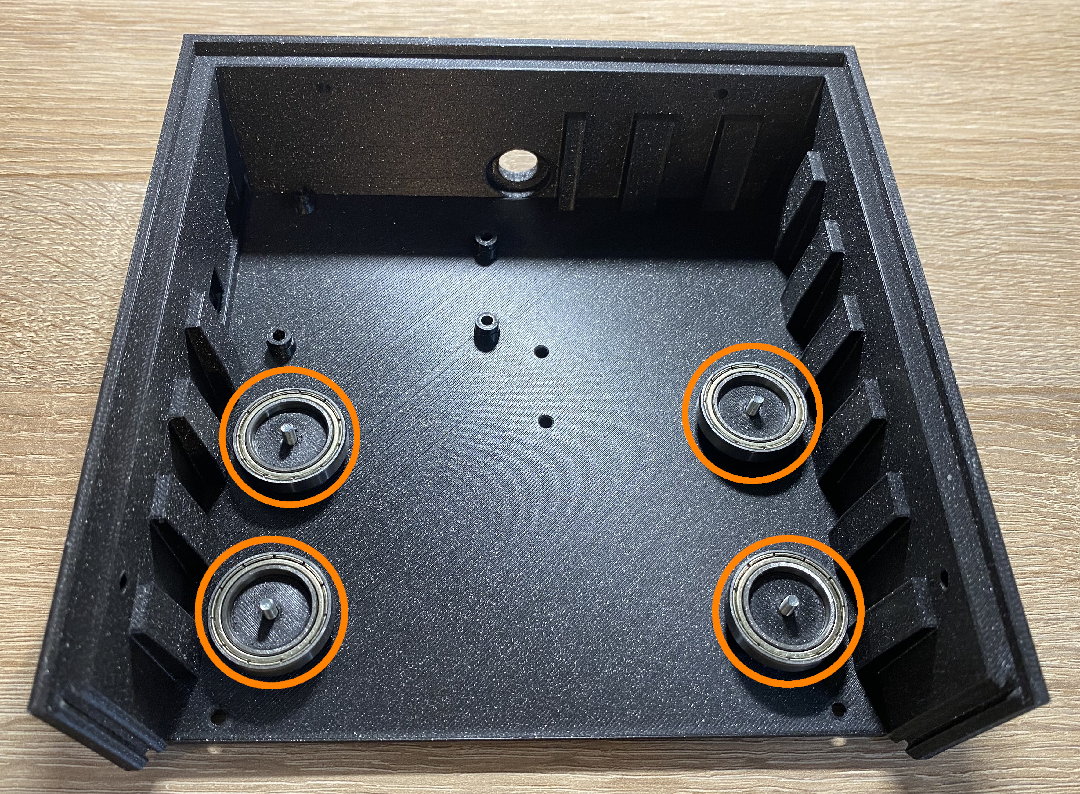
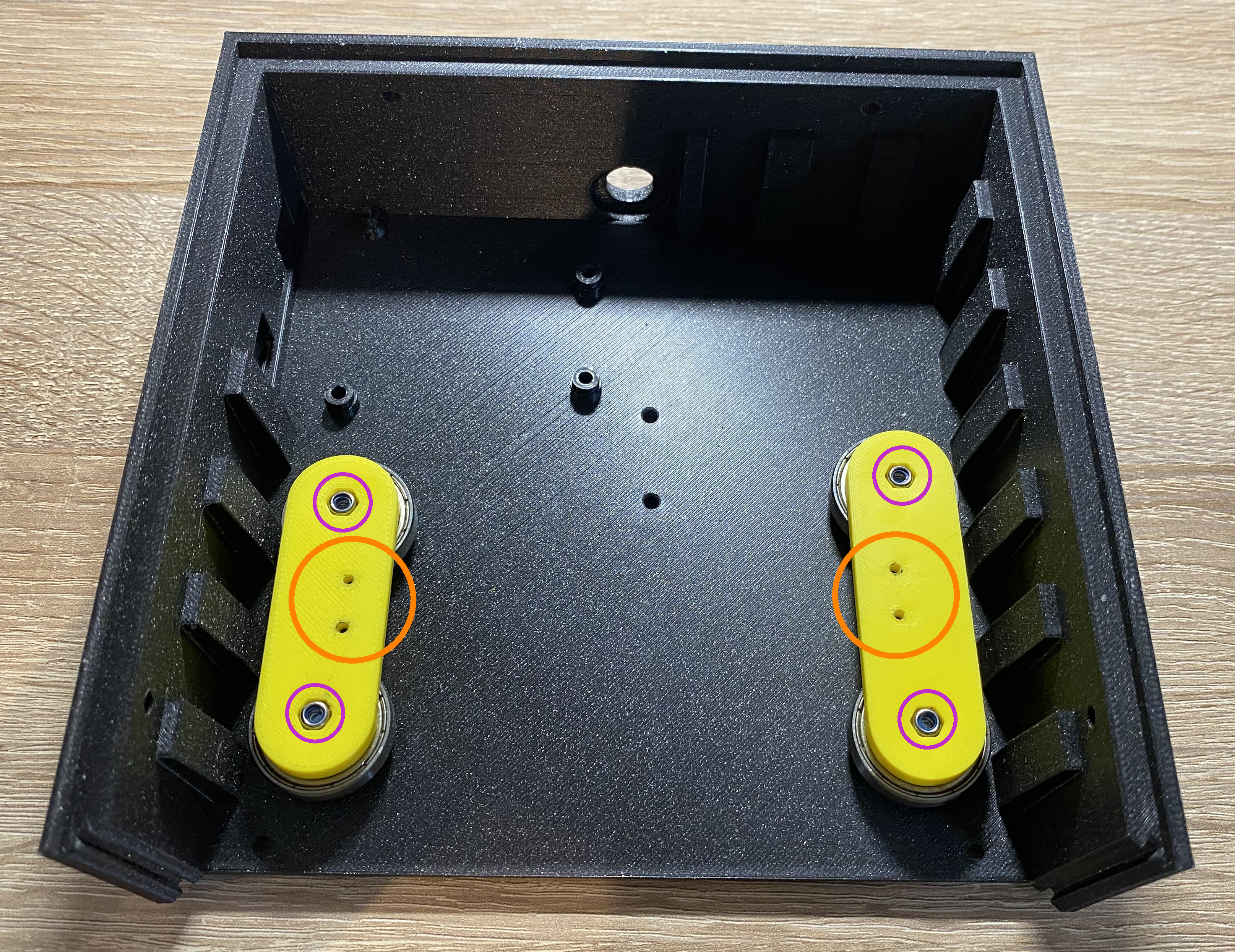
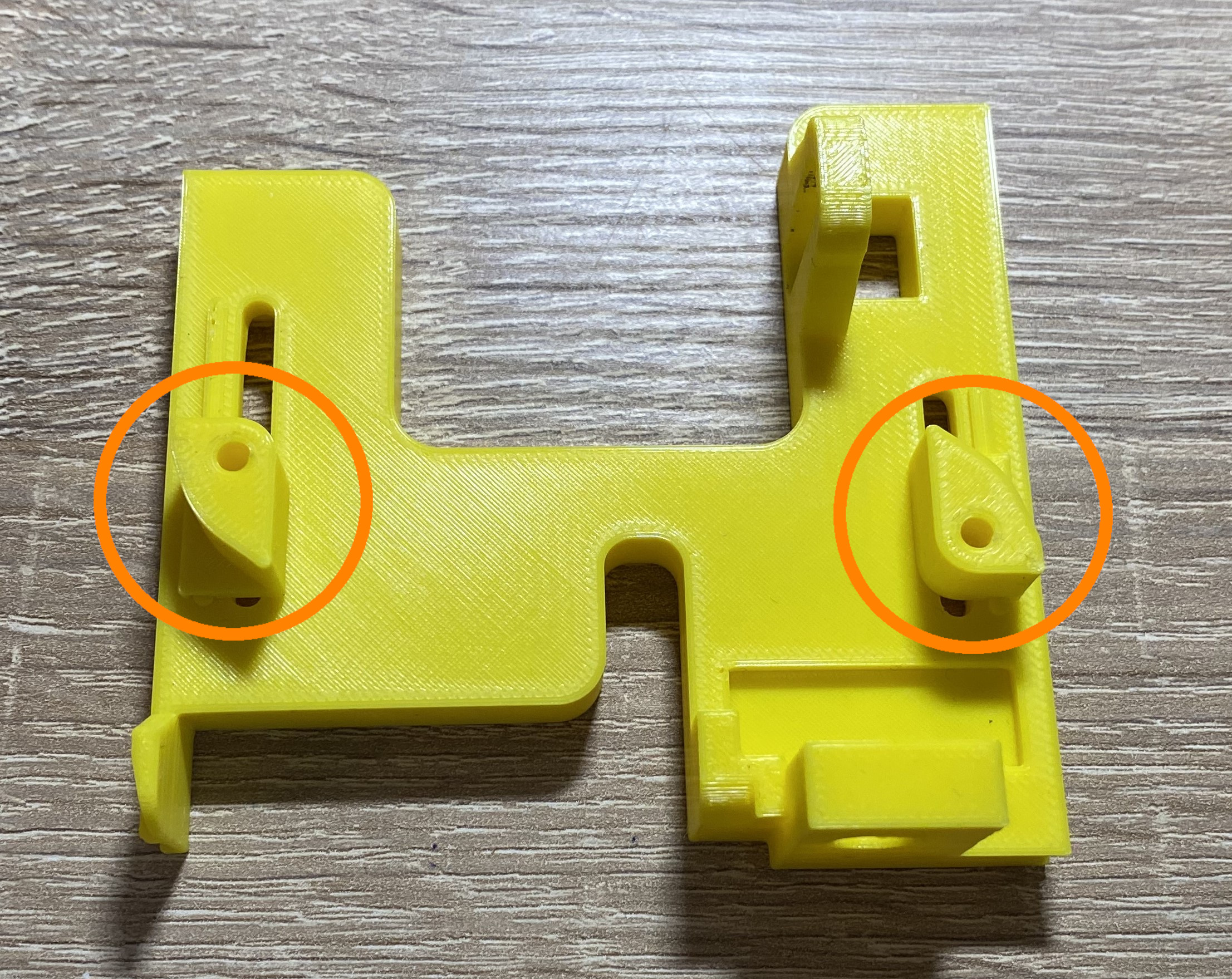
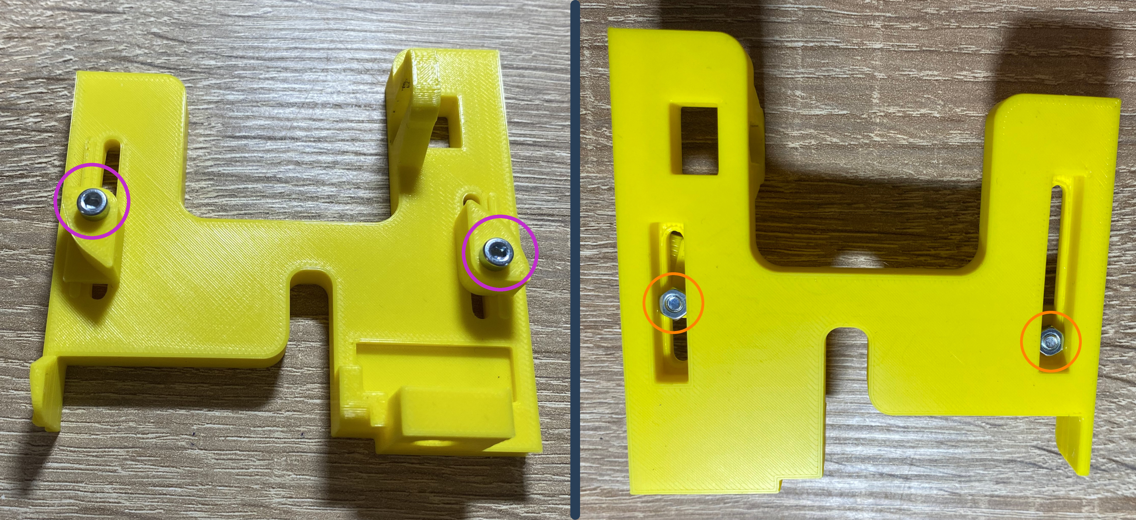
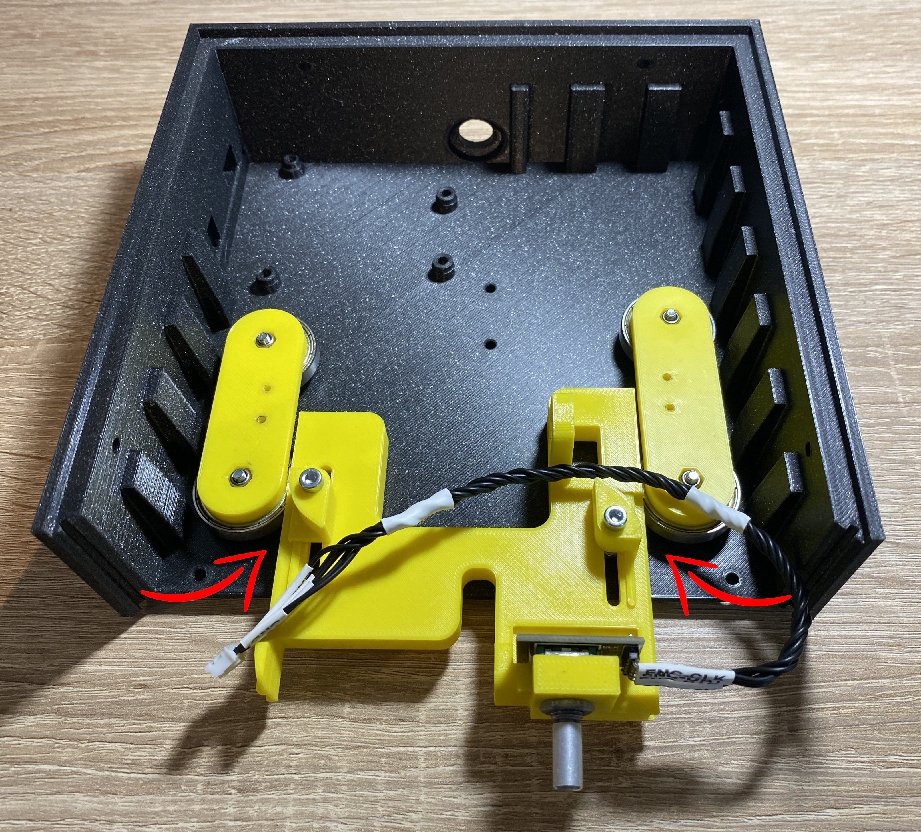
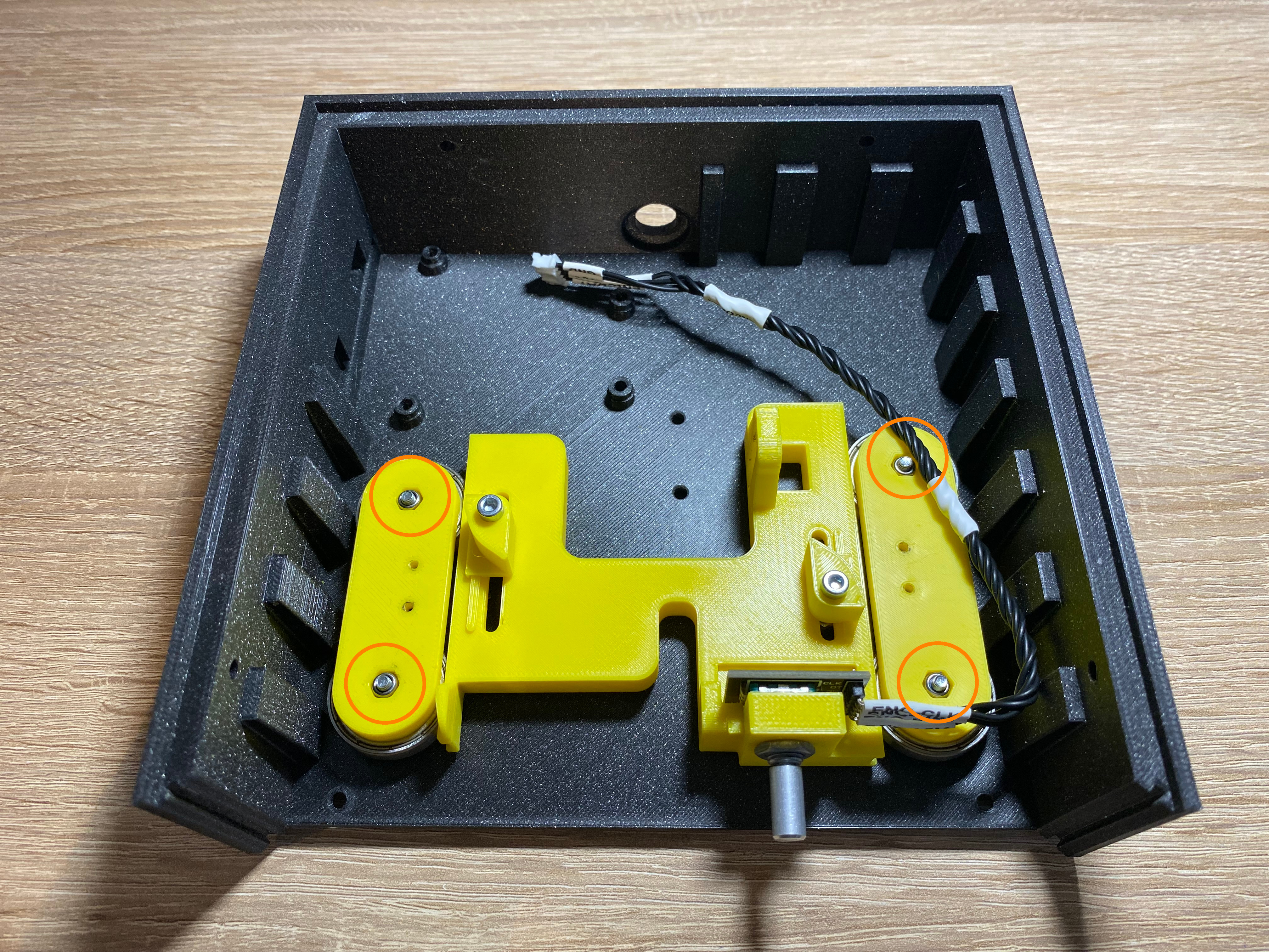
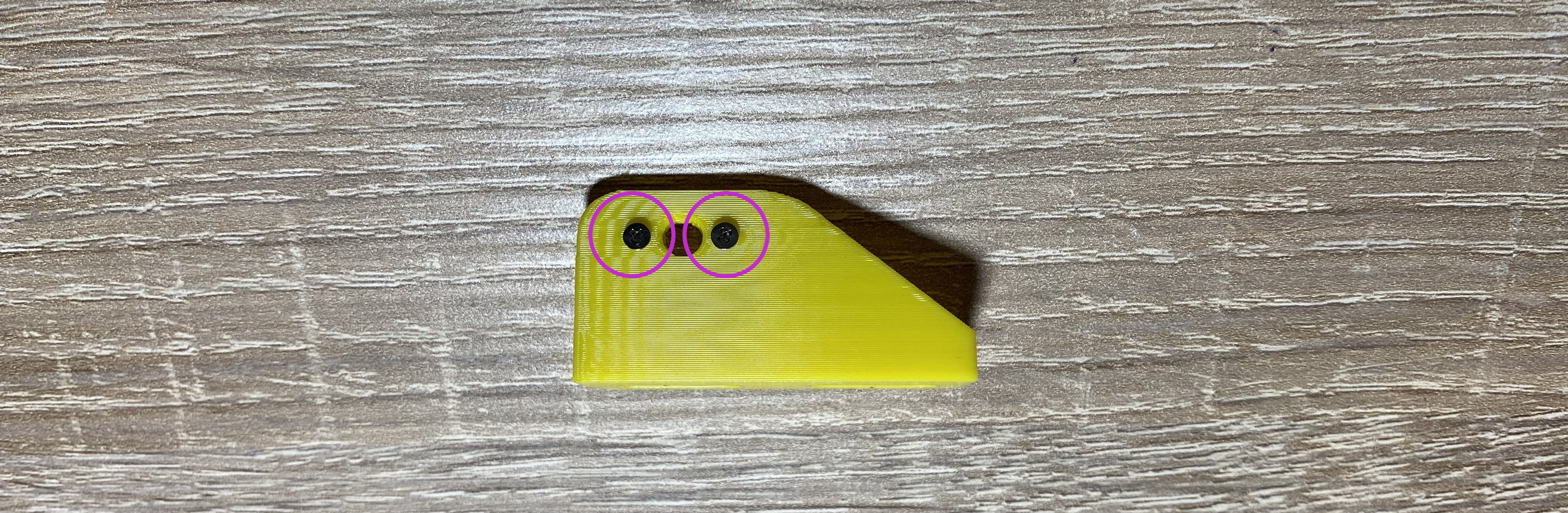
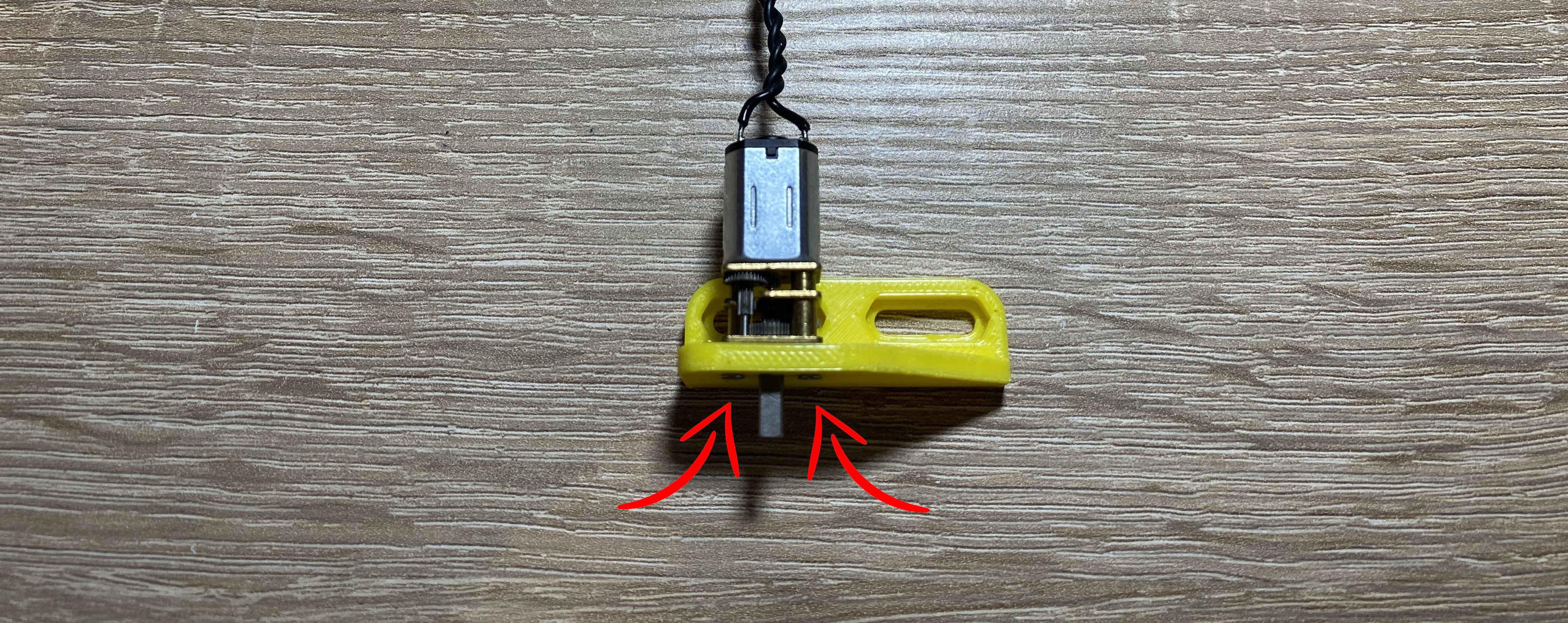
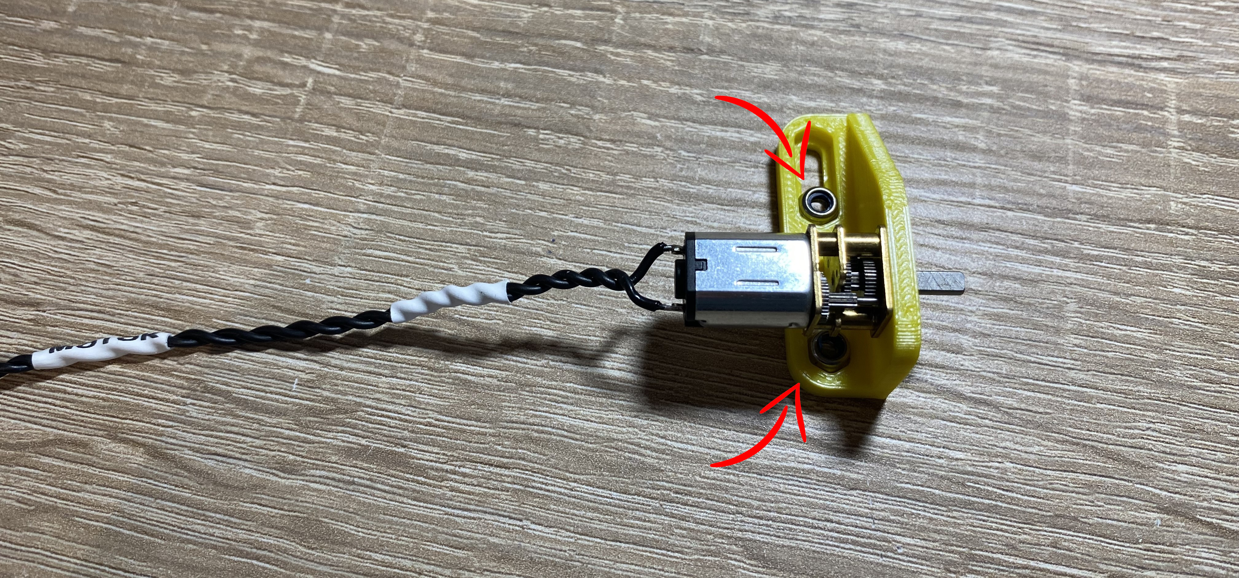
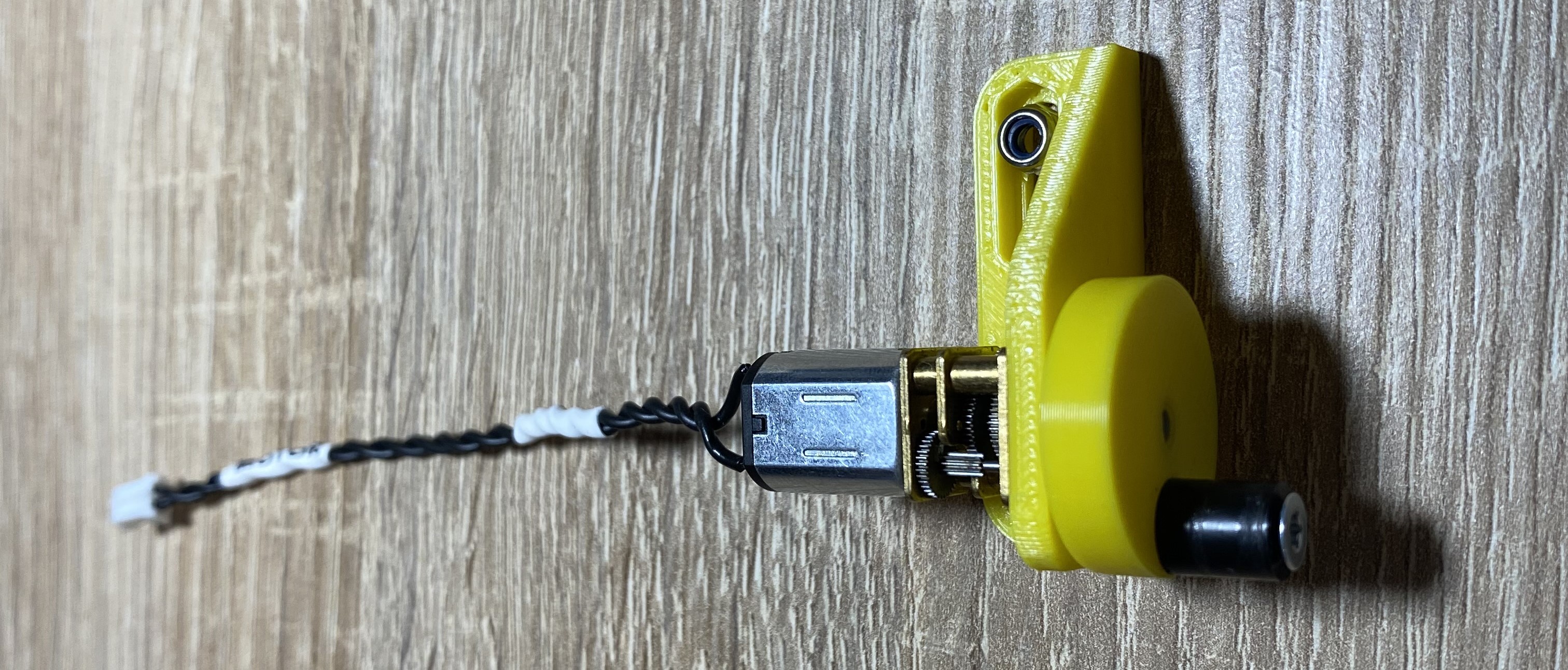
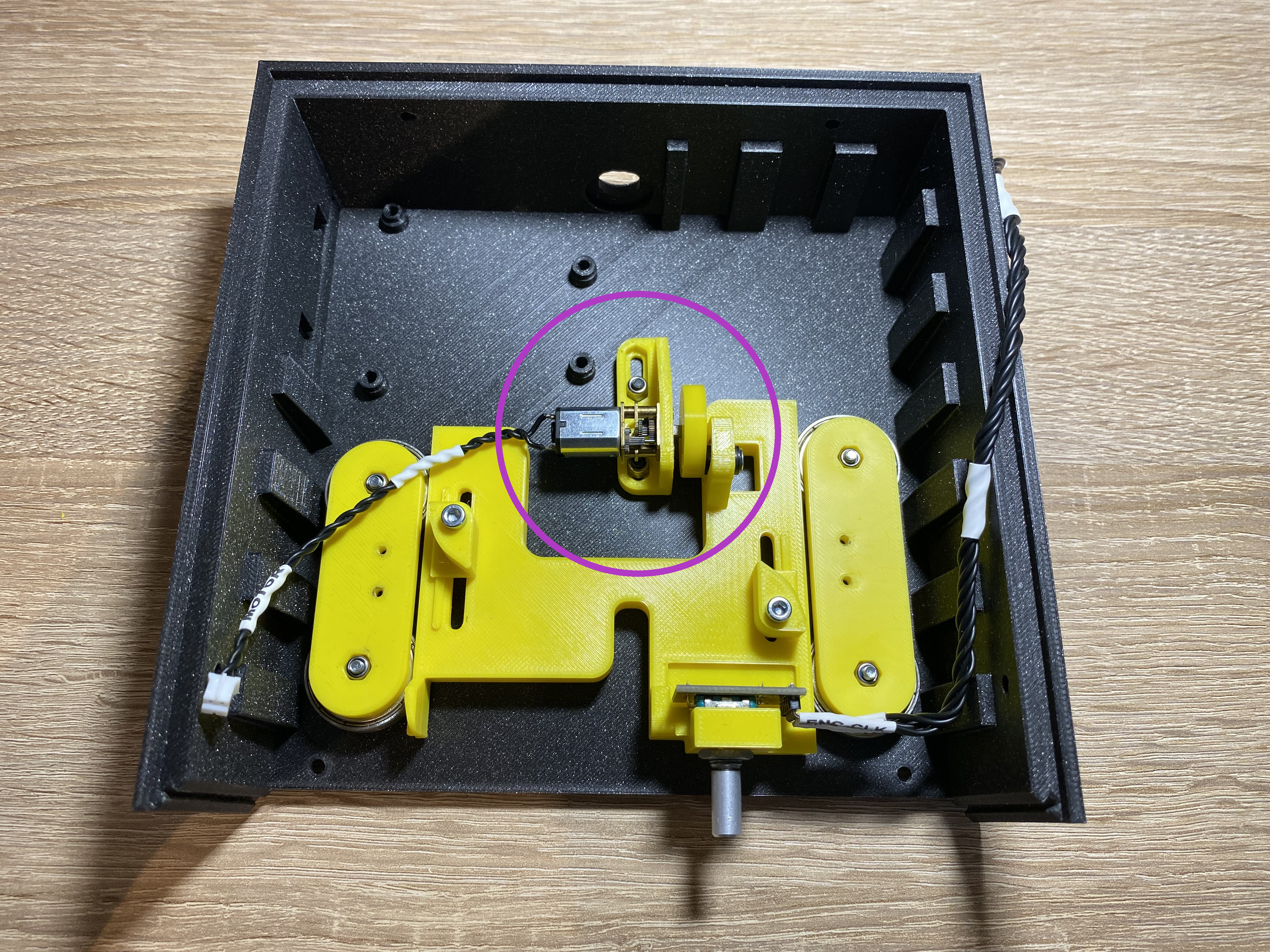
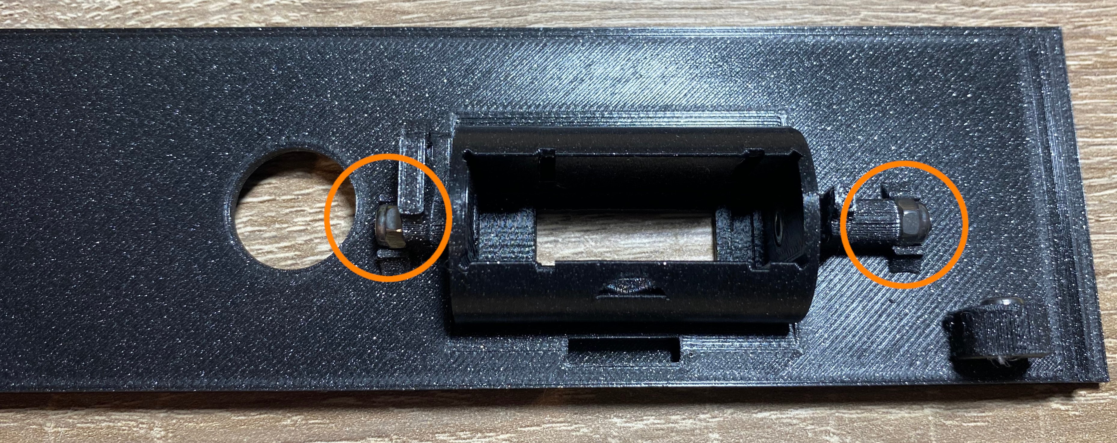
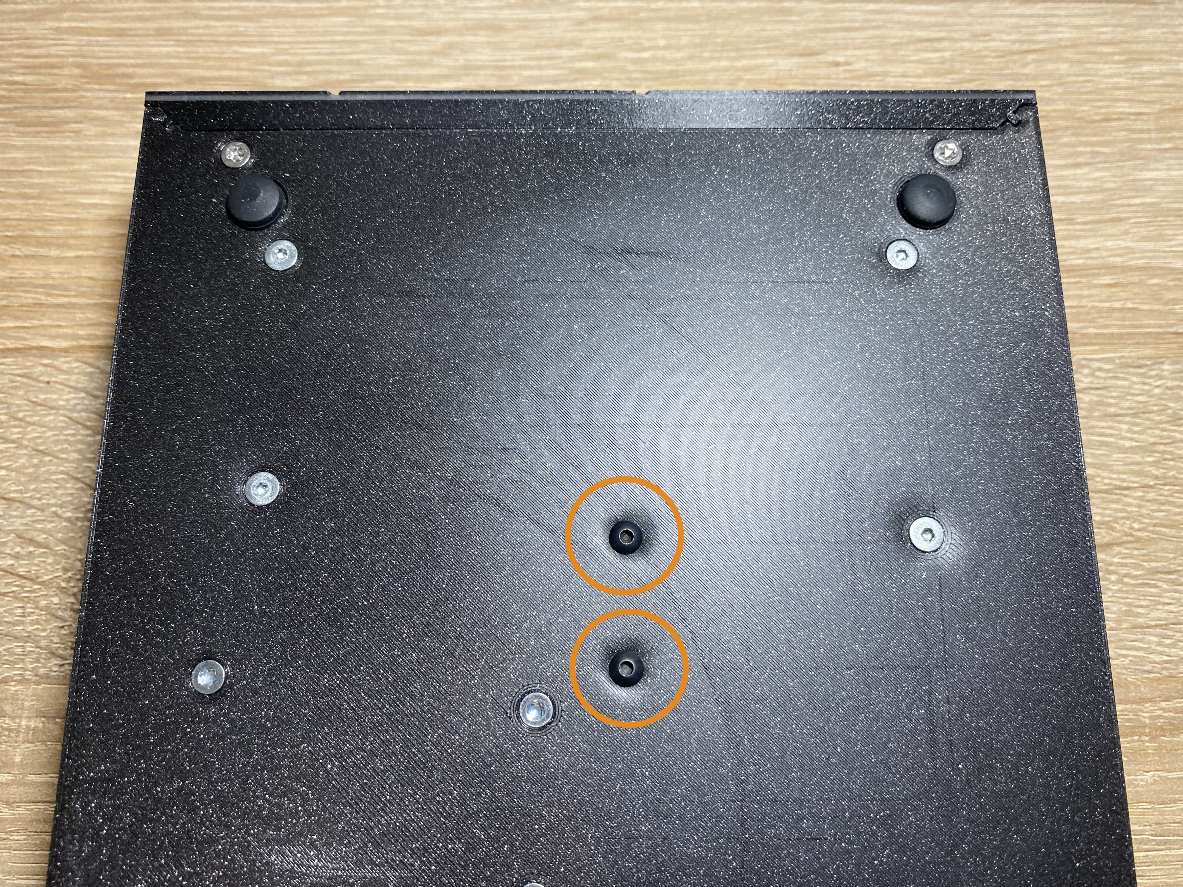
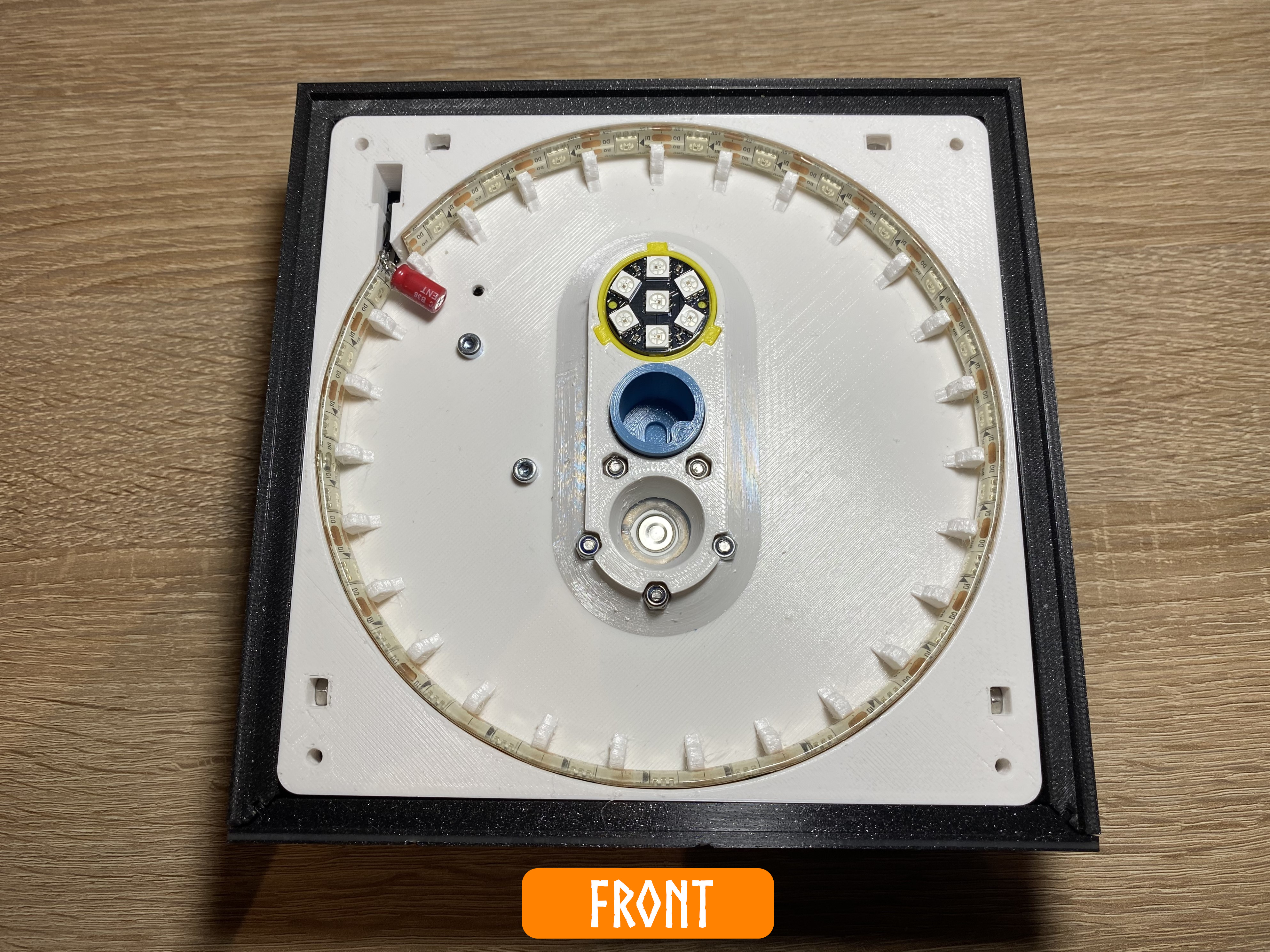
Insert the motor mount to the base. From the bottom insert two M3 x 10mm flat head crews. Tighten the two screws, but not so hard, the motor mount has to slide back and forward freely.
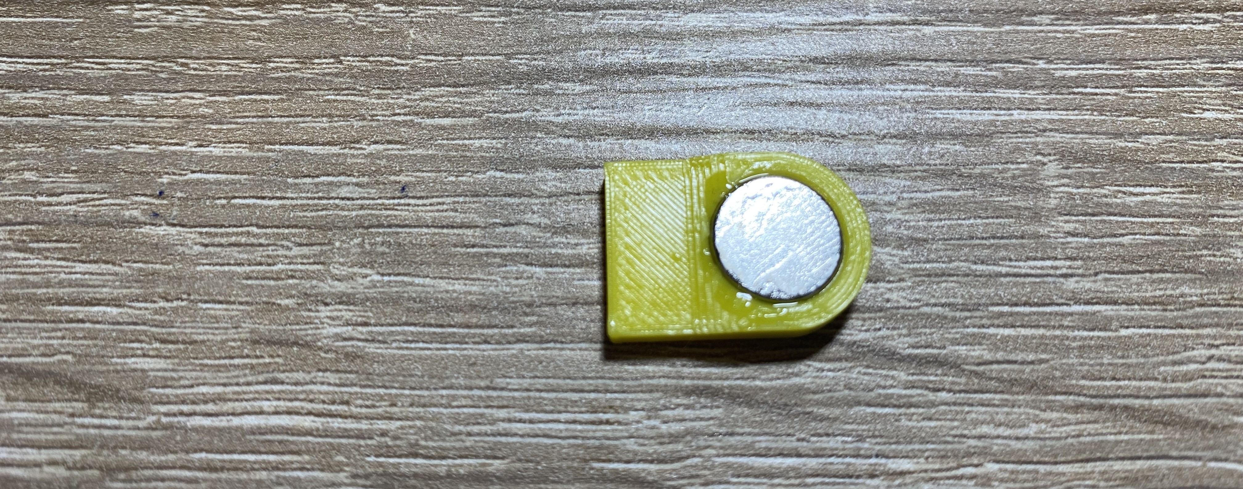
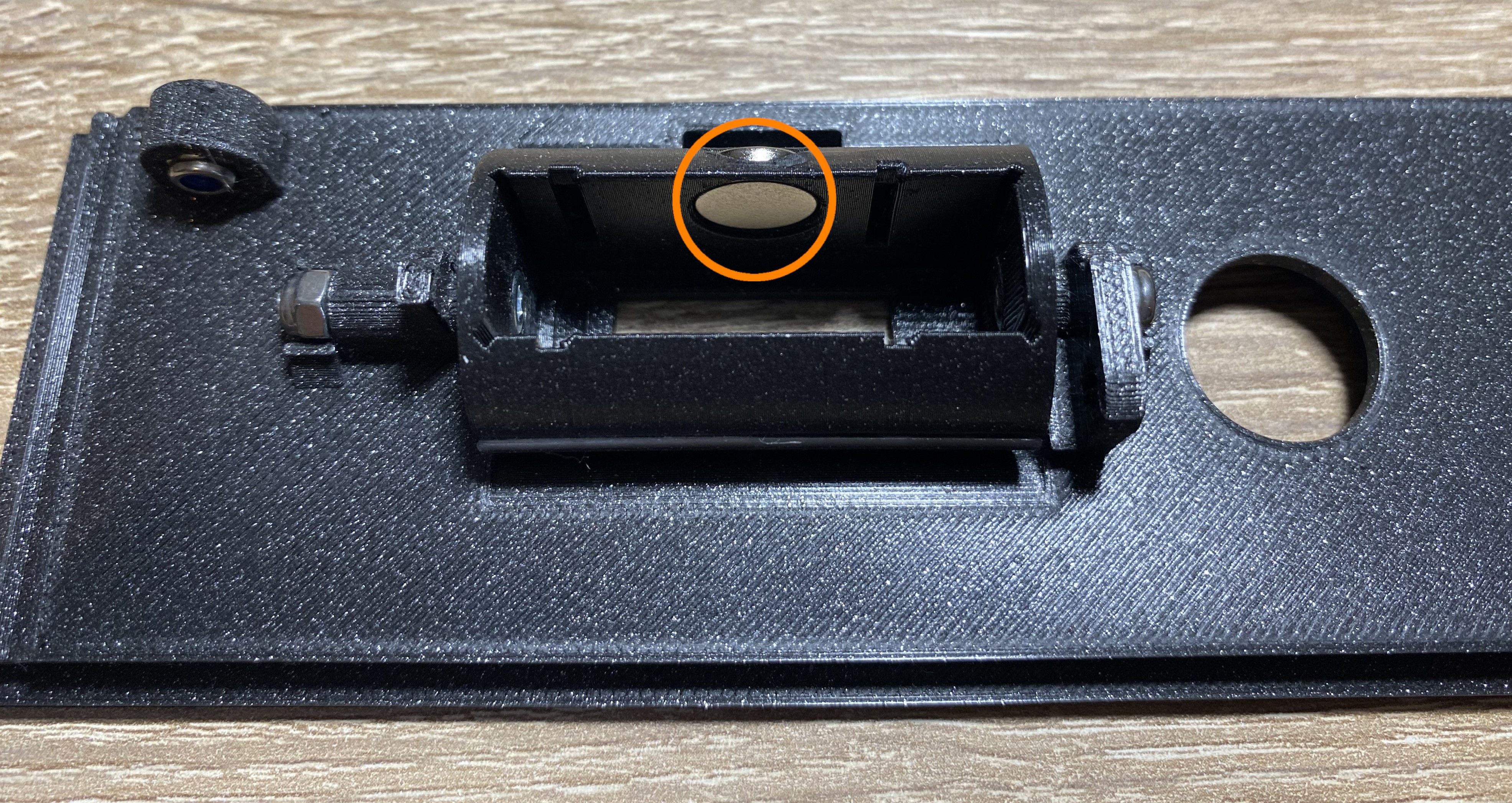
Insert the magnet holder to the slot on the front panel.
Note
If the polarity of the magnets are correct, you should see that, the display holder closes itself. The magnet on the front panel, should push up the magnet inside the display holder.
If the magnet polarity wrong, just flip the magnet inside the display holder and try it again.
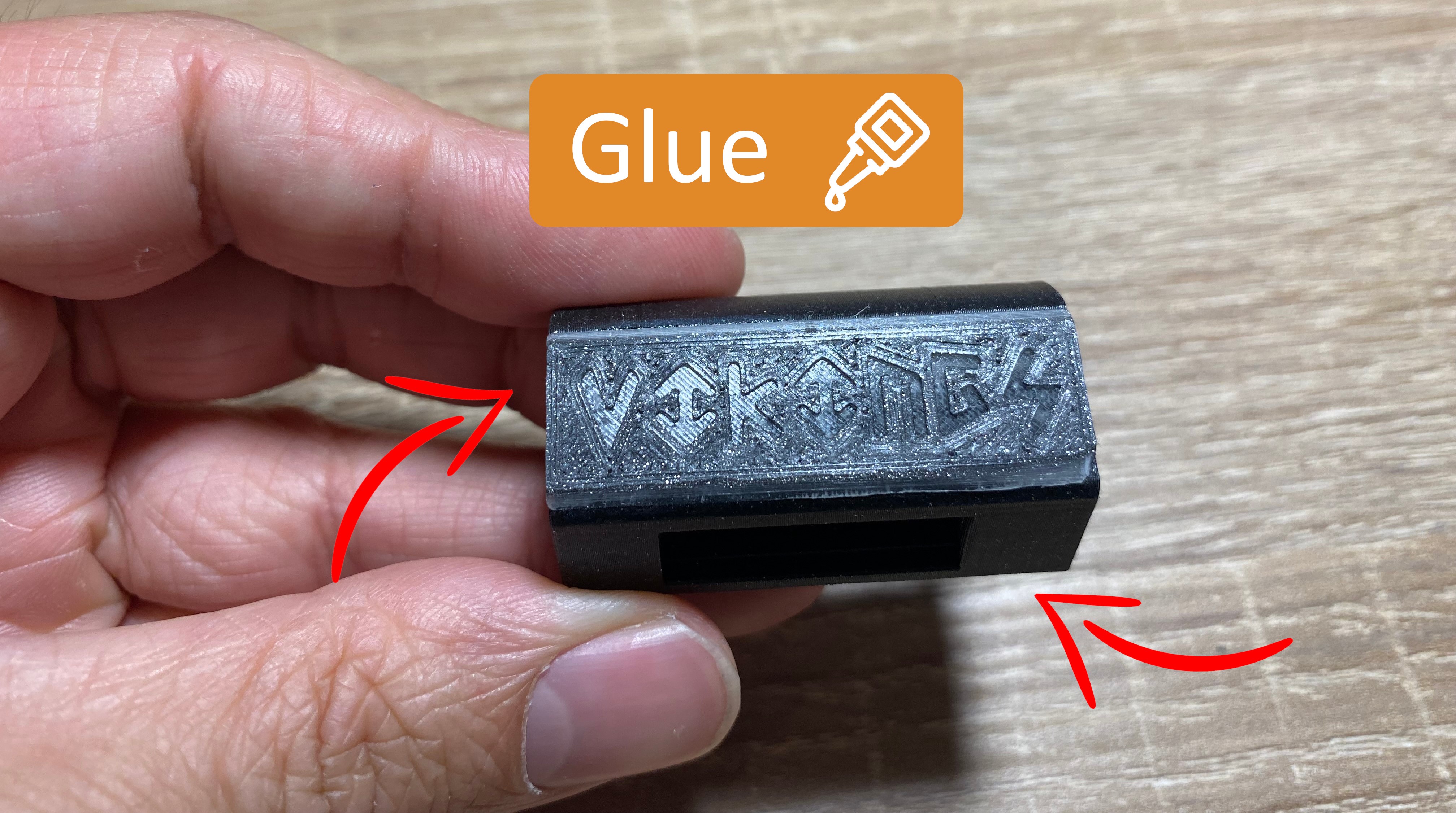
After you have tested the display holder and it's working fine, you can glue the magnet holder into the front panel, and the magnet inside the display holder.
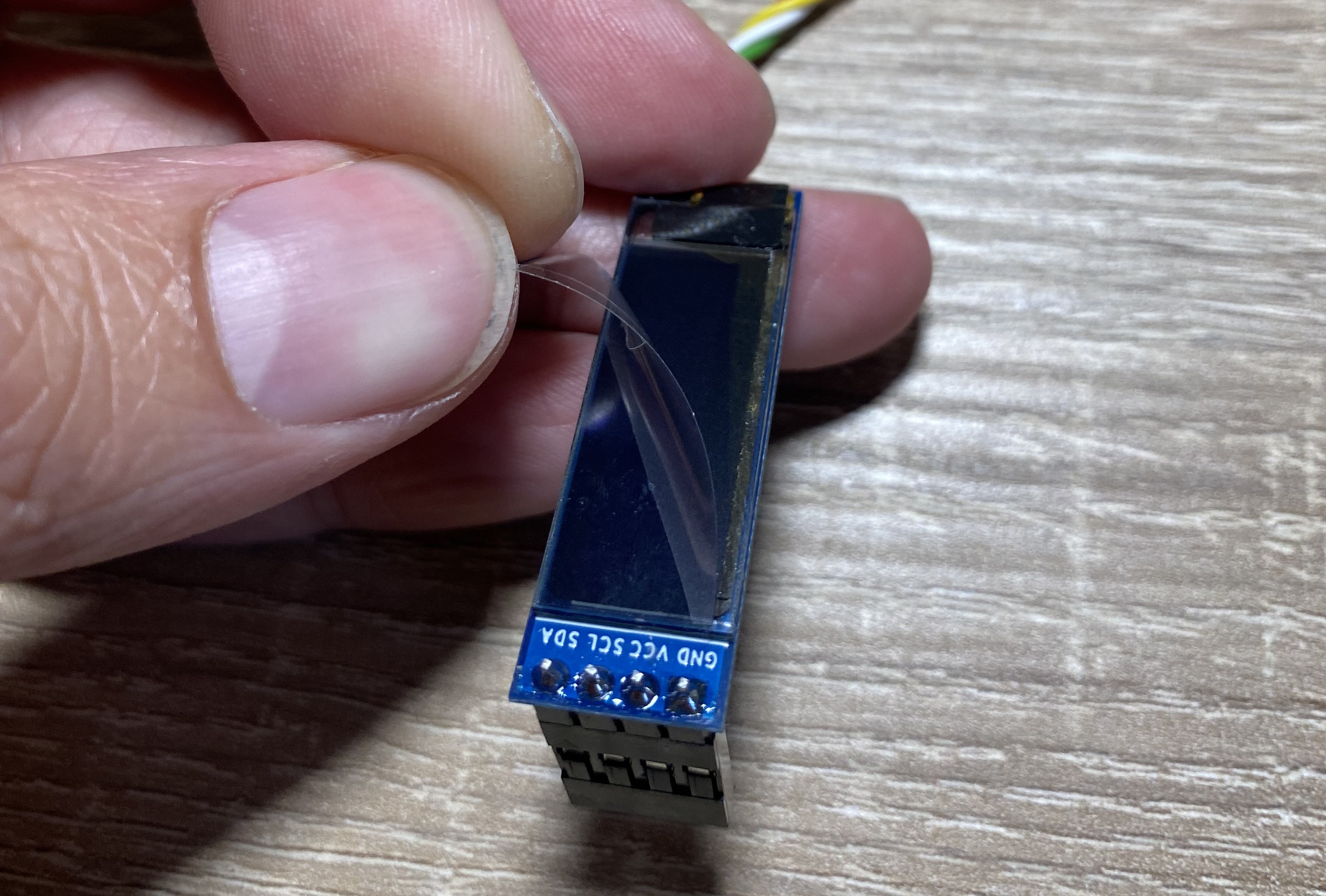
Step 39 - Peel Off Display Cover
Peel Off Display Cover
Peel off the protecting foil from the oled display.
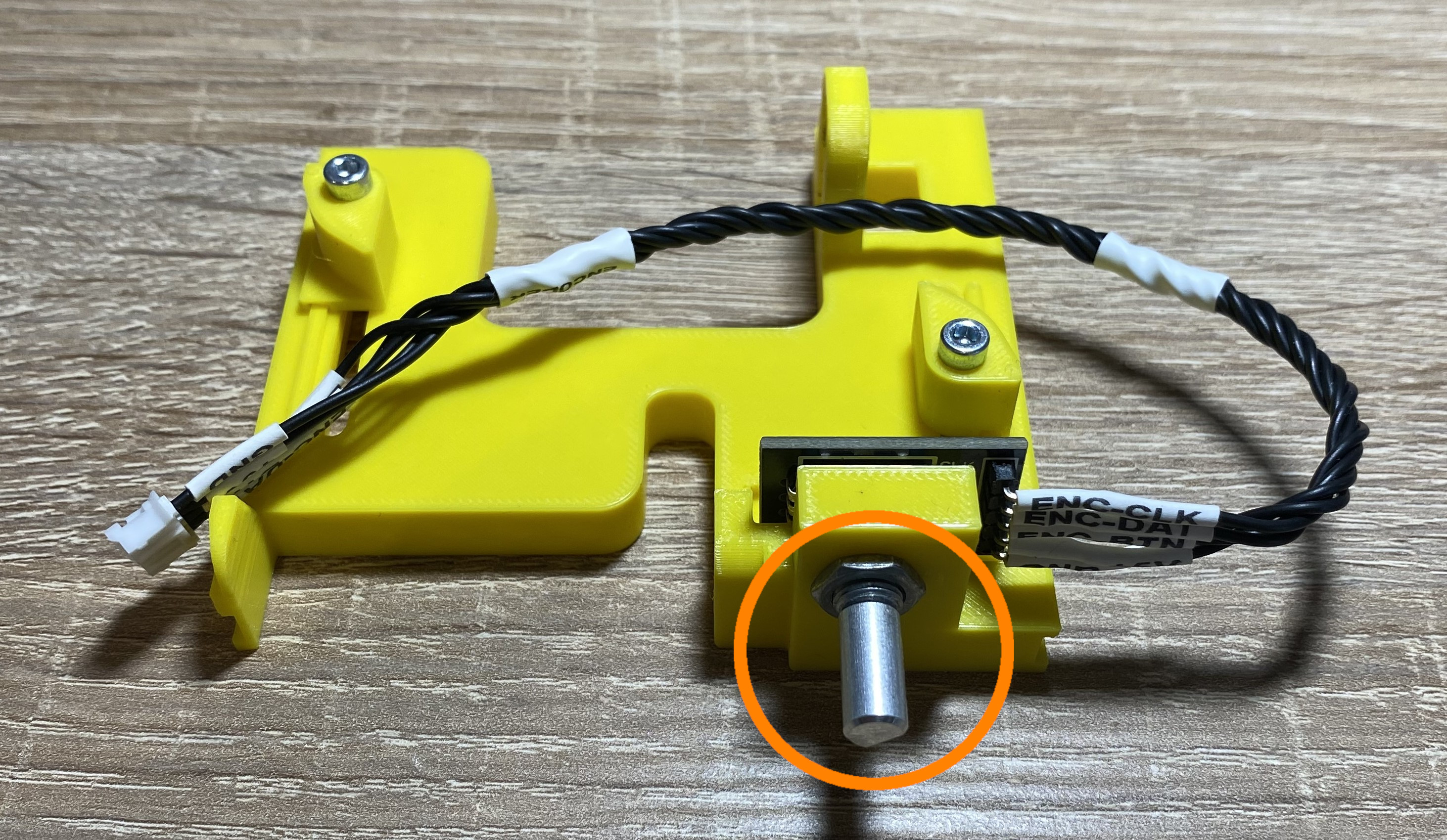
Slowly rotate the eccentric shaft to the back position.
Step 43 - Insert Front
Insert Front
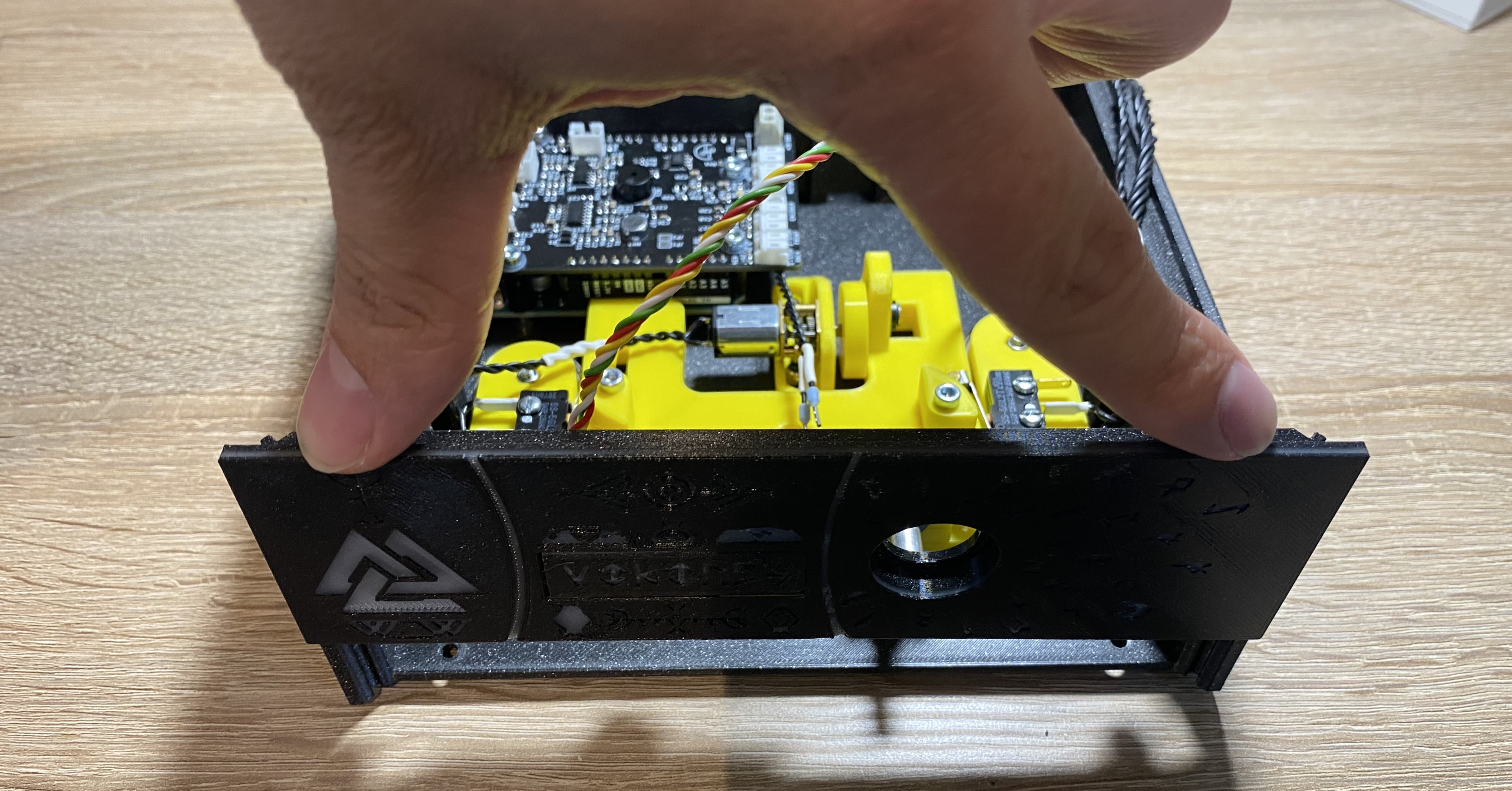
Gently slide the front to the base.
Note
The tolerances are tight, but it should slide in with a bit force. If it doesn't, clean up the parts with an exacto knife.
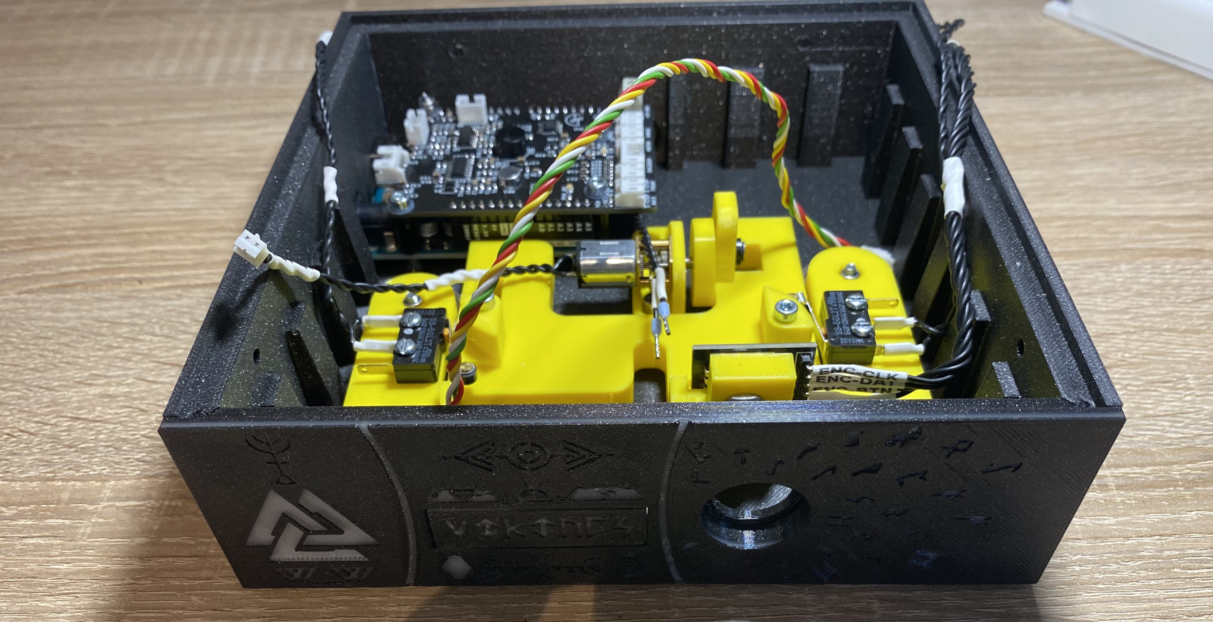
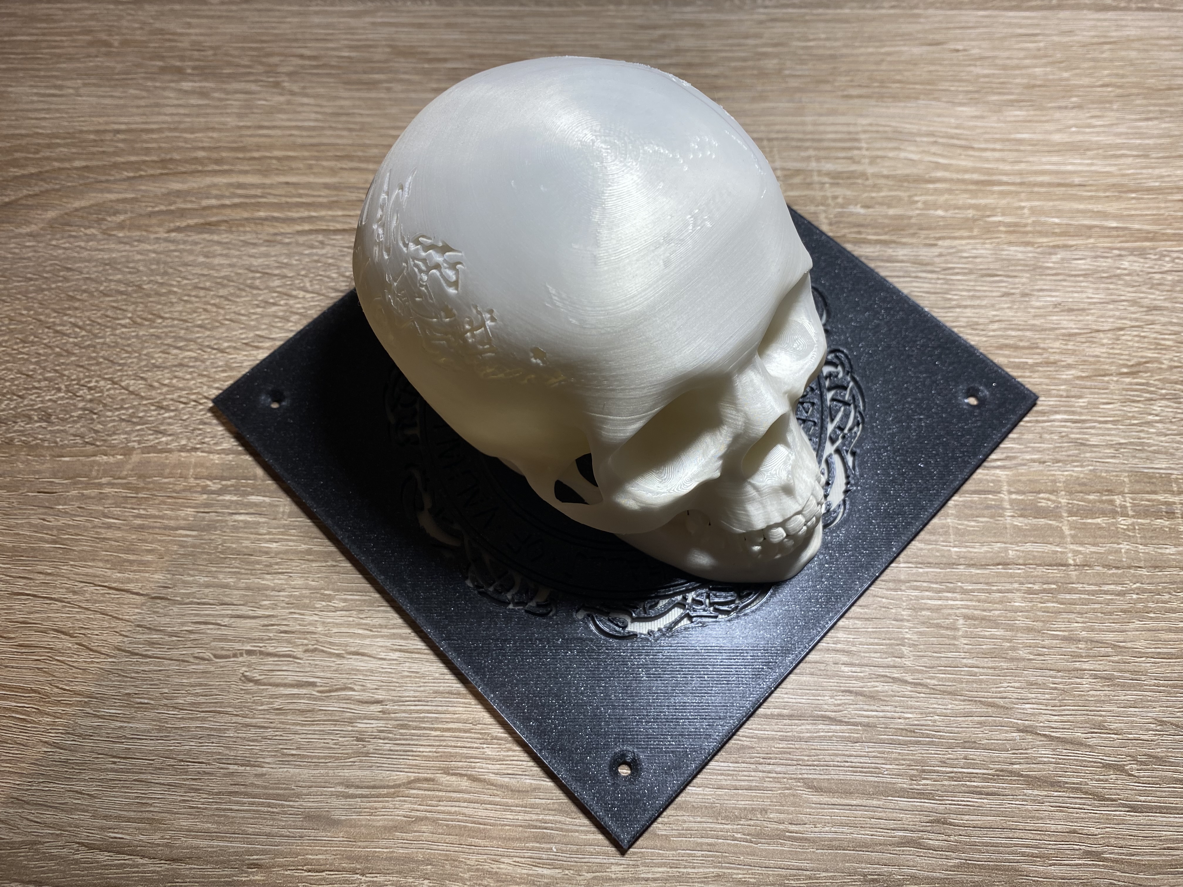
Result
It should look like this.
Step 44 - Lock Front
Lock Front
Precondition
Required parts:
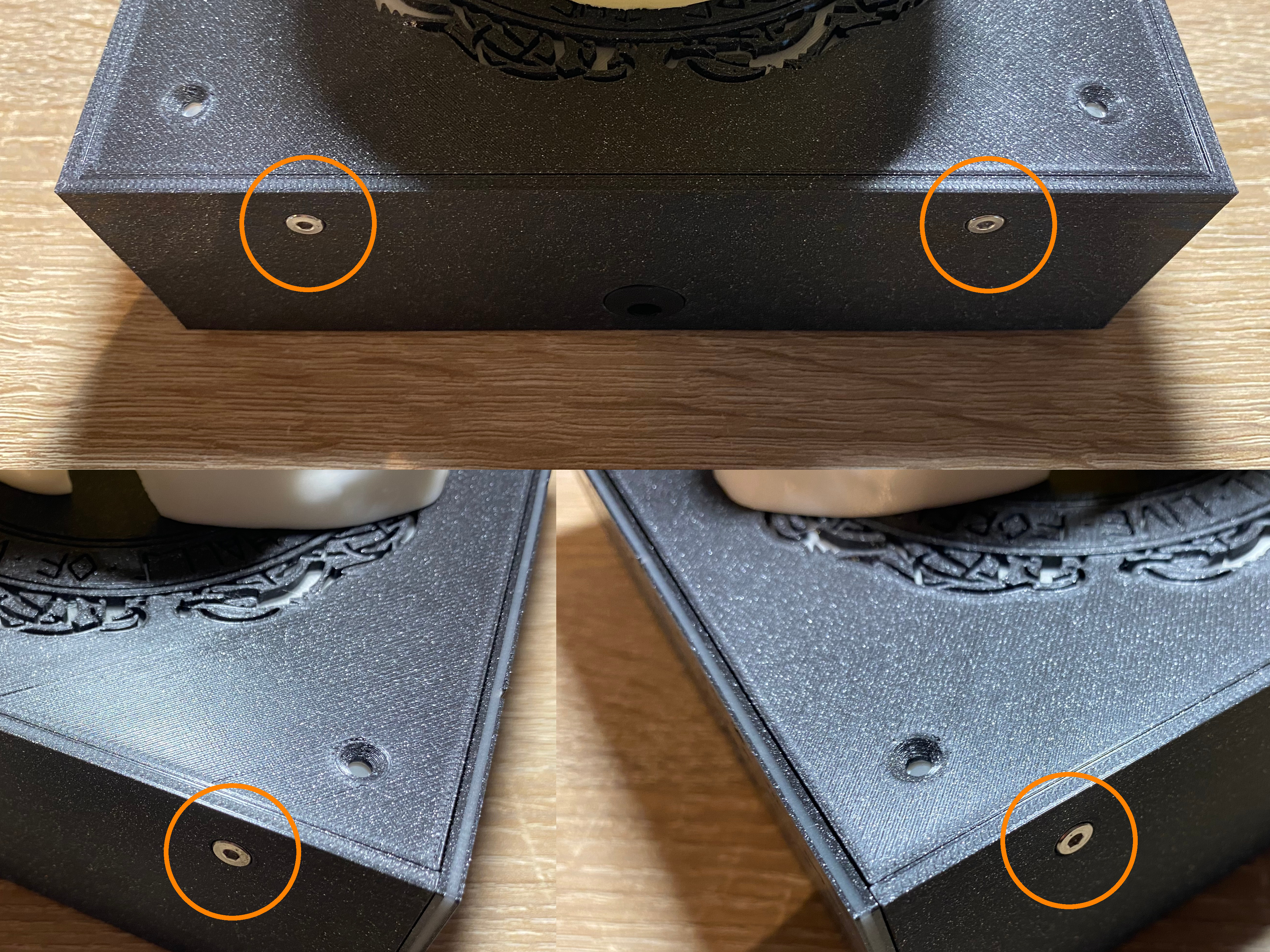
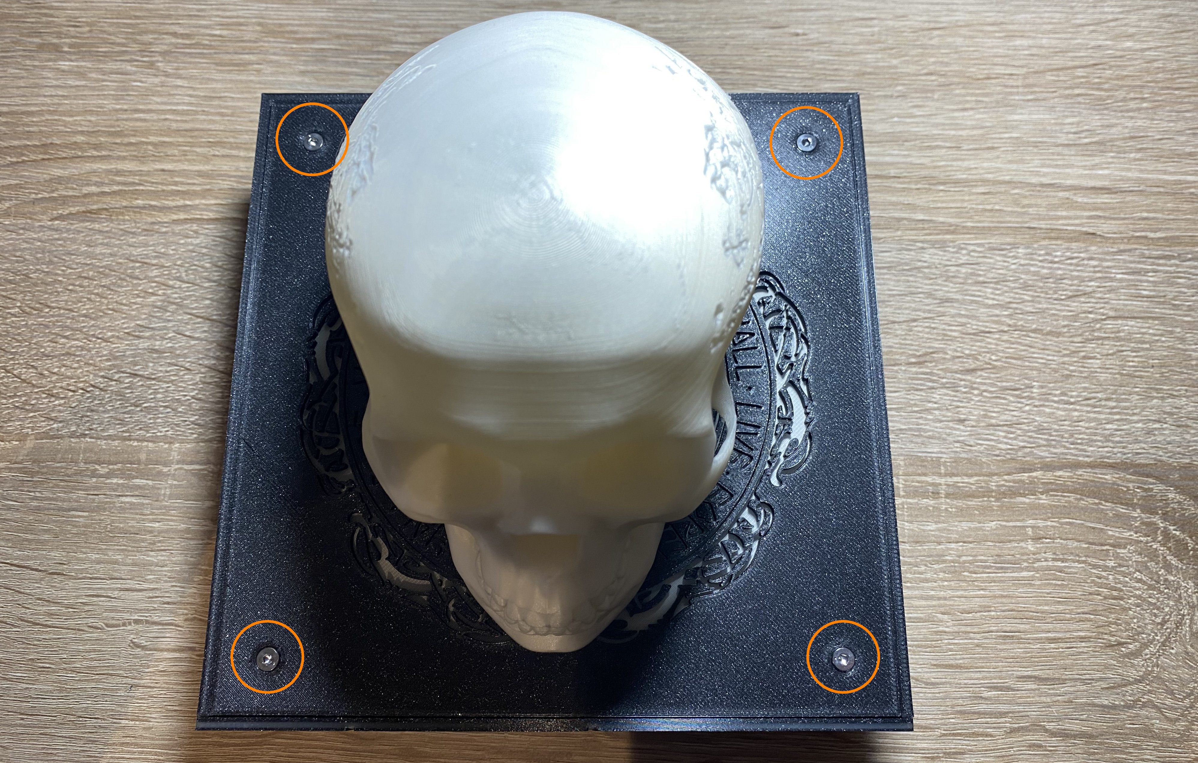
M3 x 12mm FHCS - 2pcs
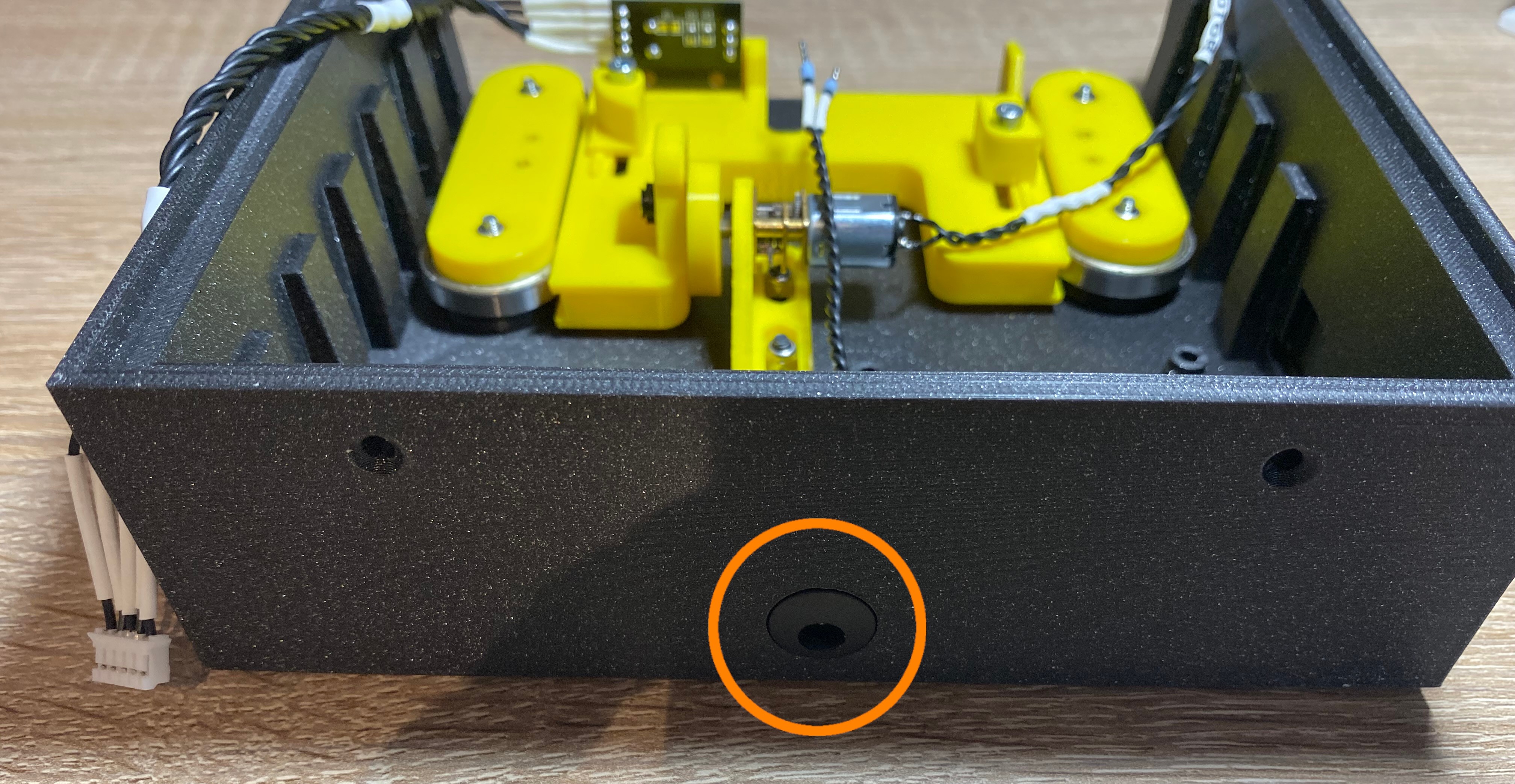
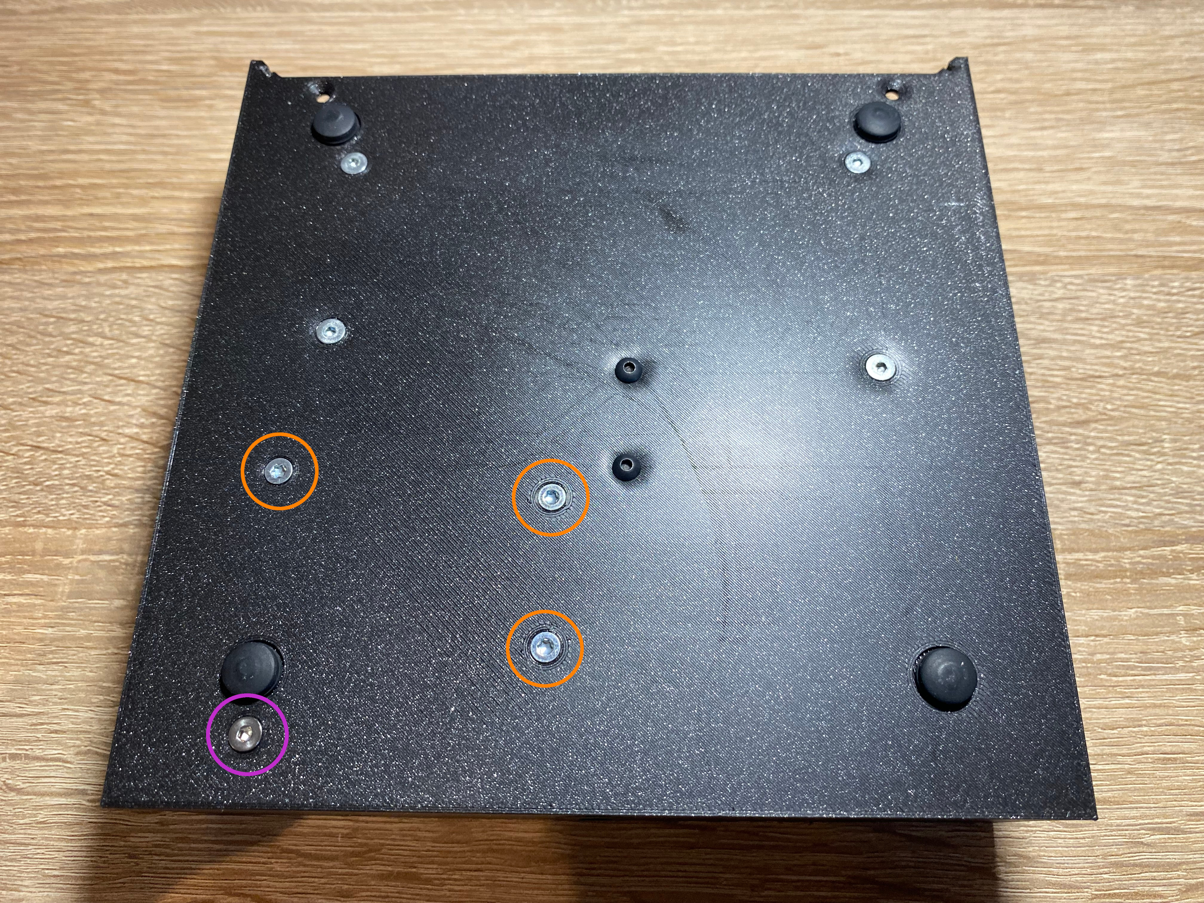
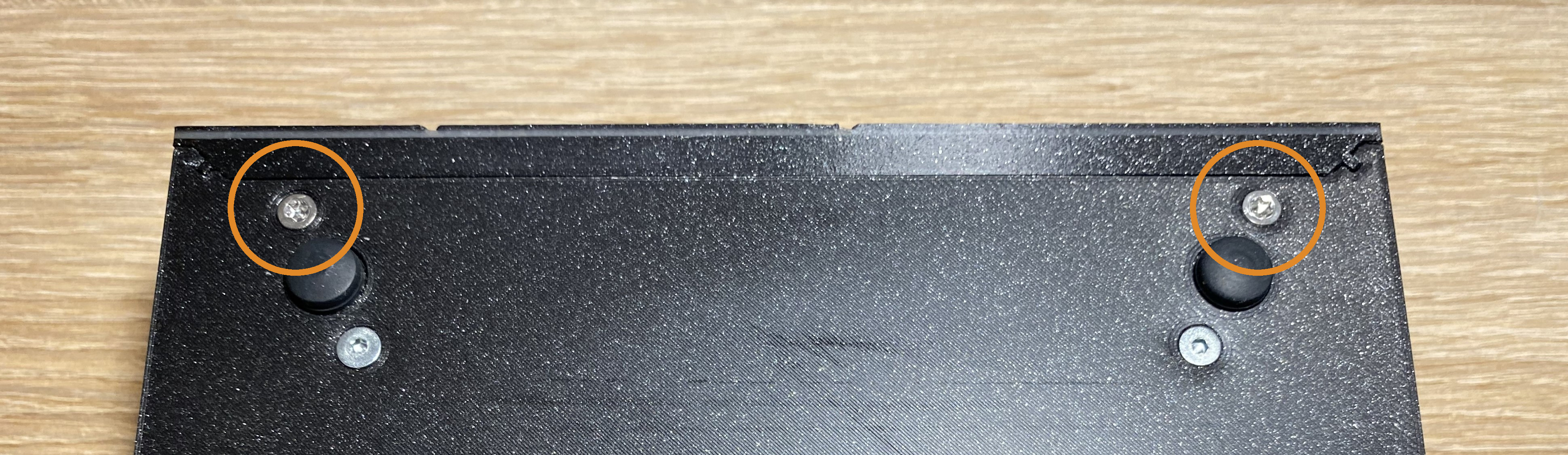
Tighten the screws on the bottom to lock the front panel.
Step 45 - Rotate Shaft Front
Rotate Shaft Front
Slowly rotate the eccentric shaft to the front position.
Step 46 - Push Motor Mount Front
Push Motor Mount Front
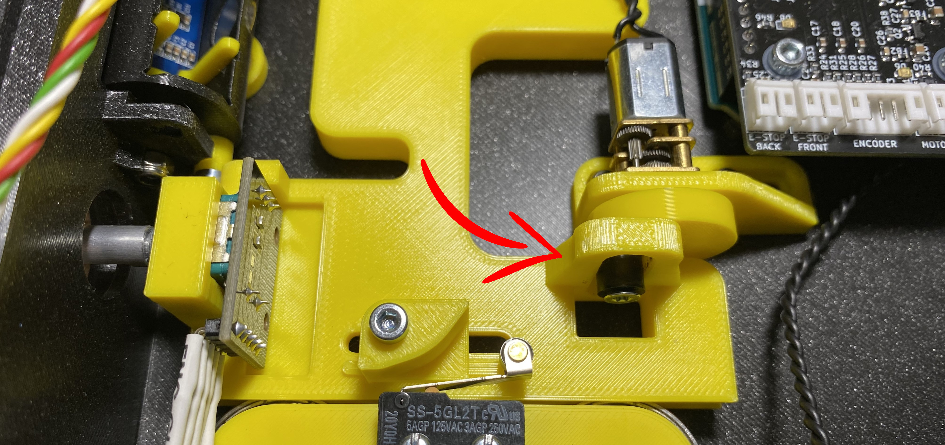
Gently push the motor mount to the front. We have to find absolute front position.
Step 47 - Lock Motor Mount
Lock Motor Mount
Tighten the screws from the motor mount while the motor mount is pushed to the front position
If you power the motor with a bench supply( no more than 5V, and 300mA ), and crank up the voltage slowly, you should see that the mechanism opens and closes.
Note
Sorry for the color mismatch, the video captured from an early prototype. The expected behaviour is the same.
If the mechanism stuck at opening, that means the motor mount is set the wrong position, it has to be adjusted. You have to push it a bit to the back.
If the mechanism opens and closes, but the display doesn't open fully, that means the motor mount is set the wrong position, it has to be adjusted. You have to push it a bit to the front.
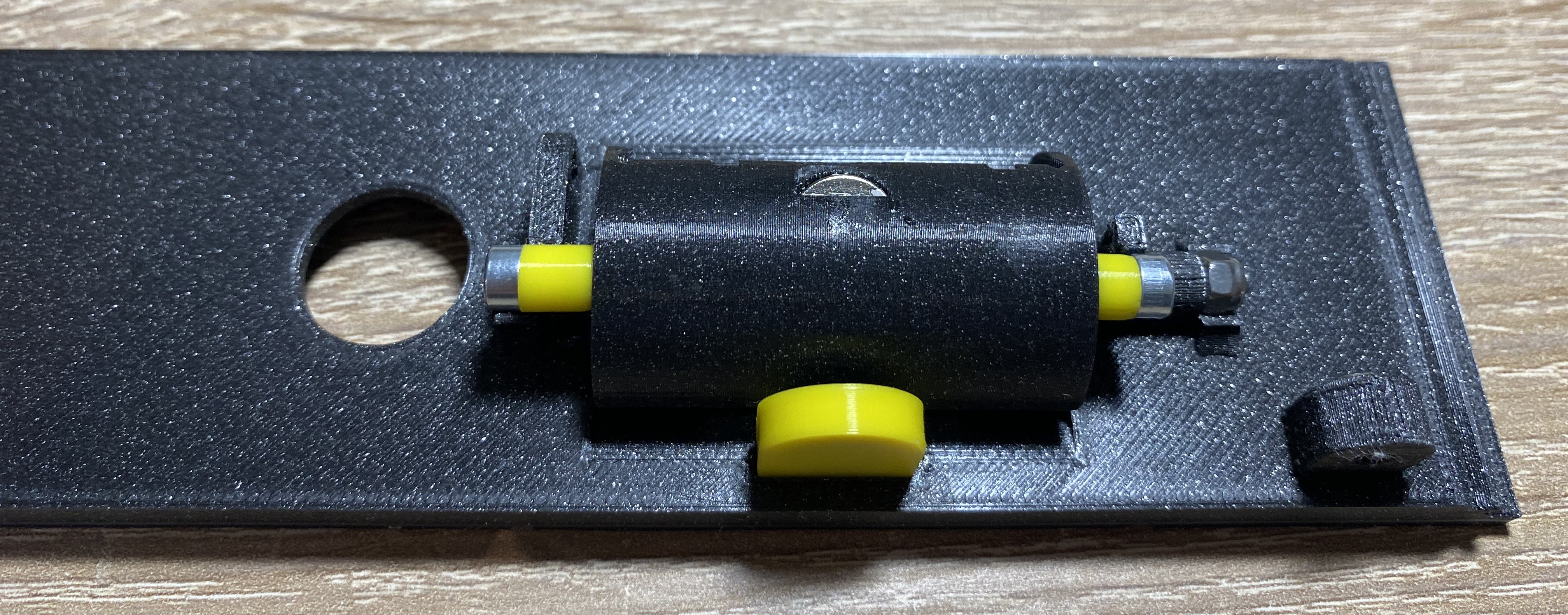
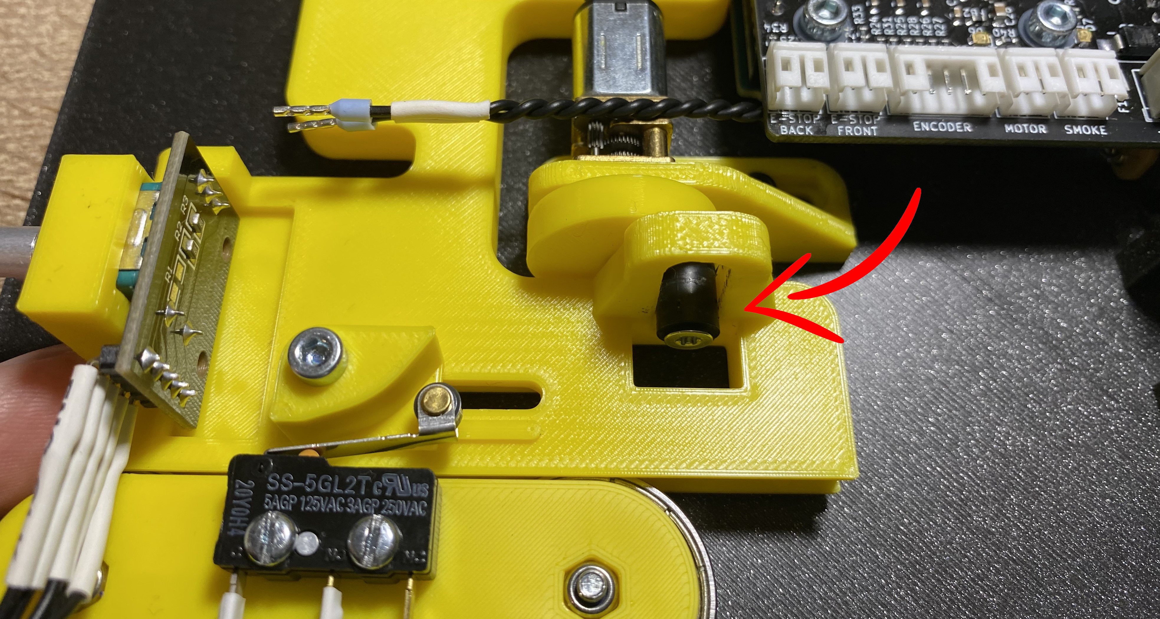
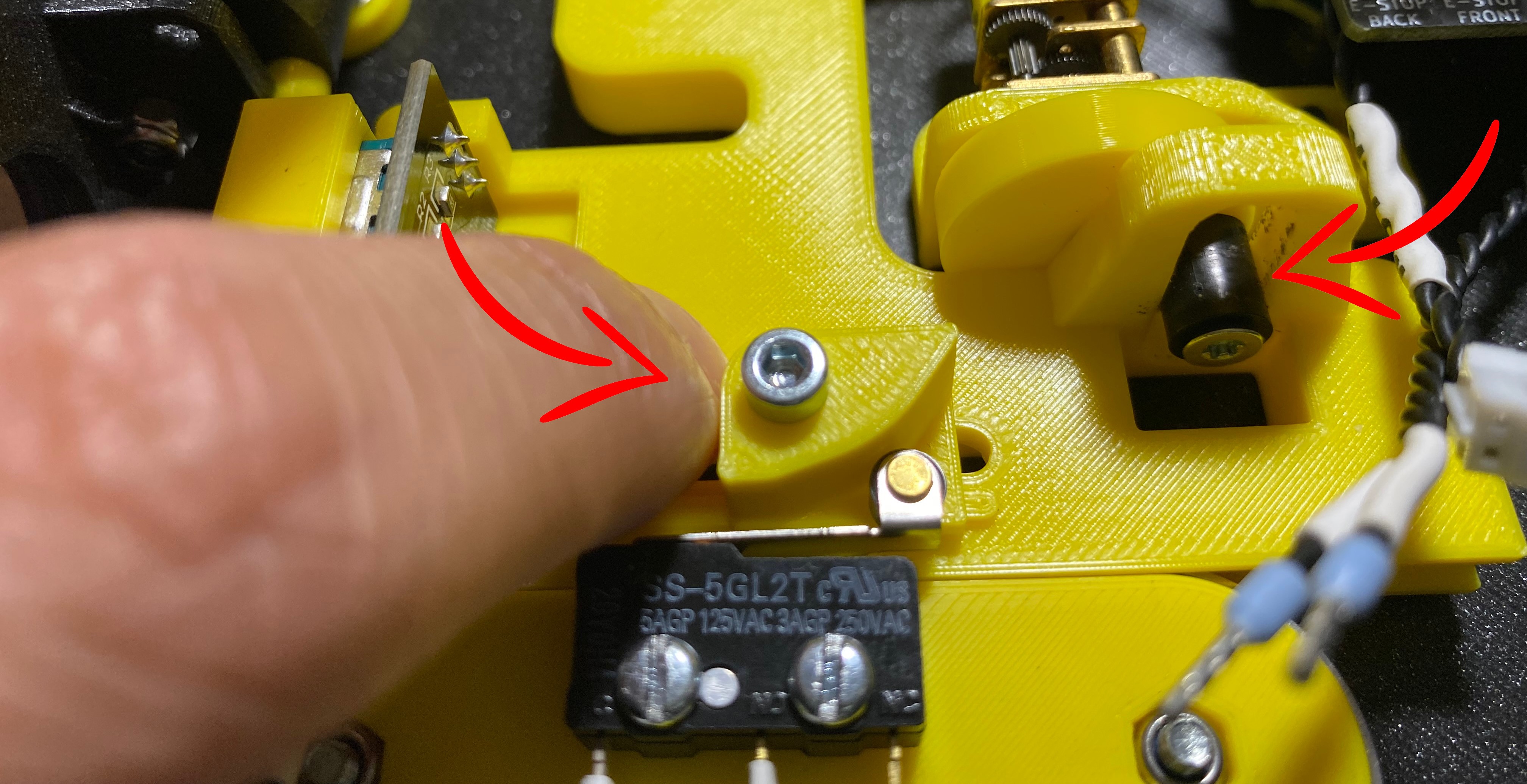
Step 48 - Adjust Back Endstop Knob
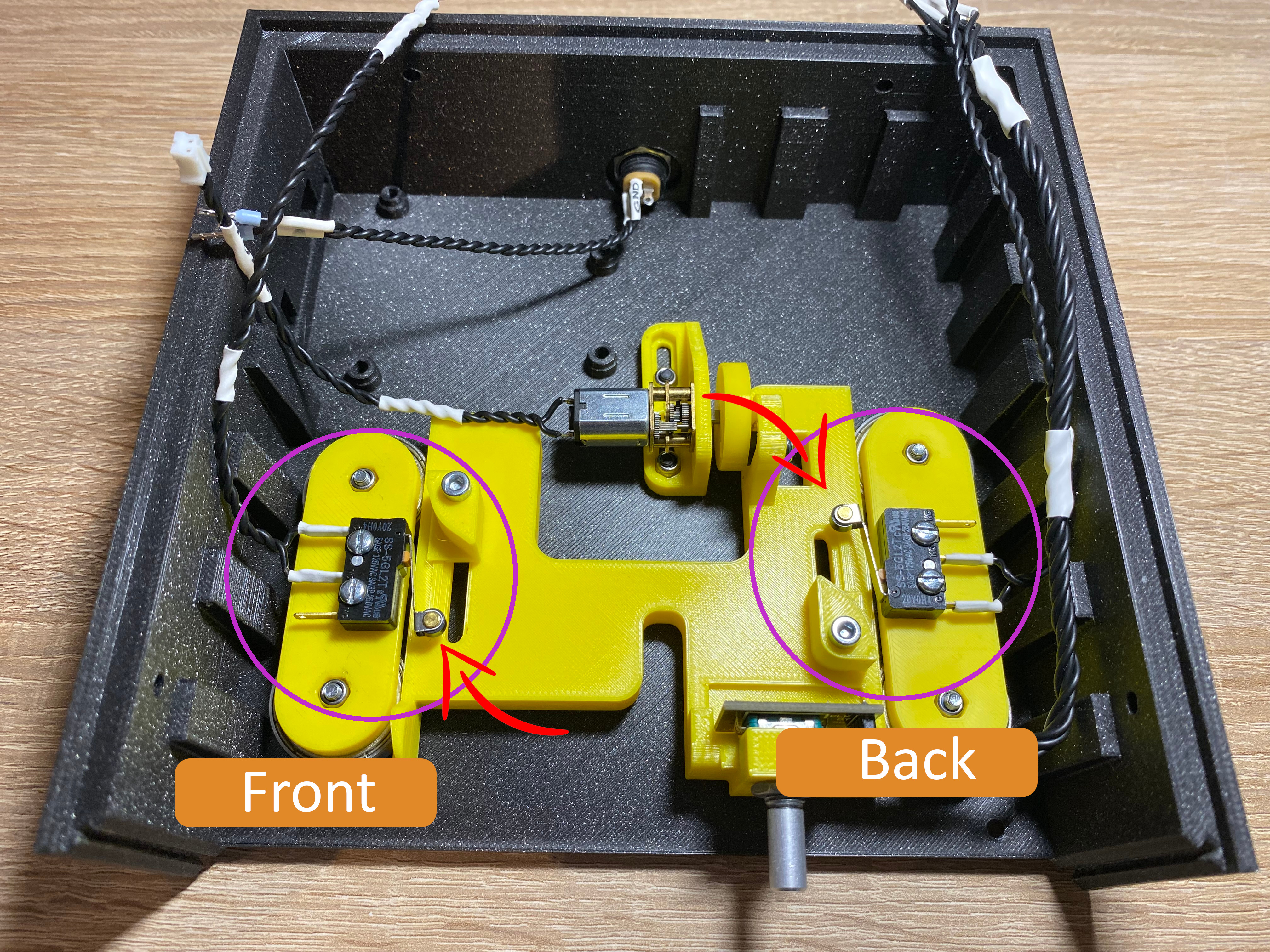
Adjust Back Endstop Knob
Slowly rotate the eccentric shaft to the back position.
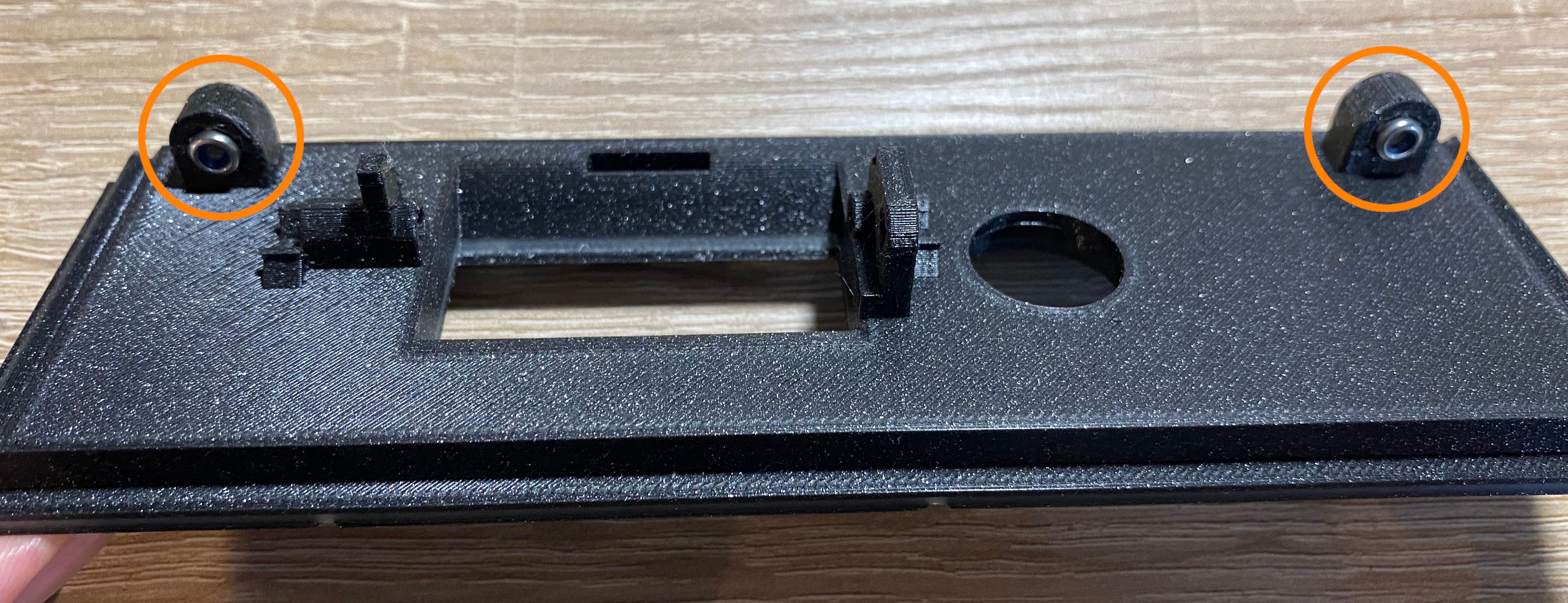
Adjust the back endstop knob position. It has to just click when the mechanism arrives to the back position.
Tighten the screw to fix the knob.
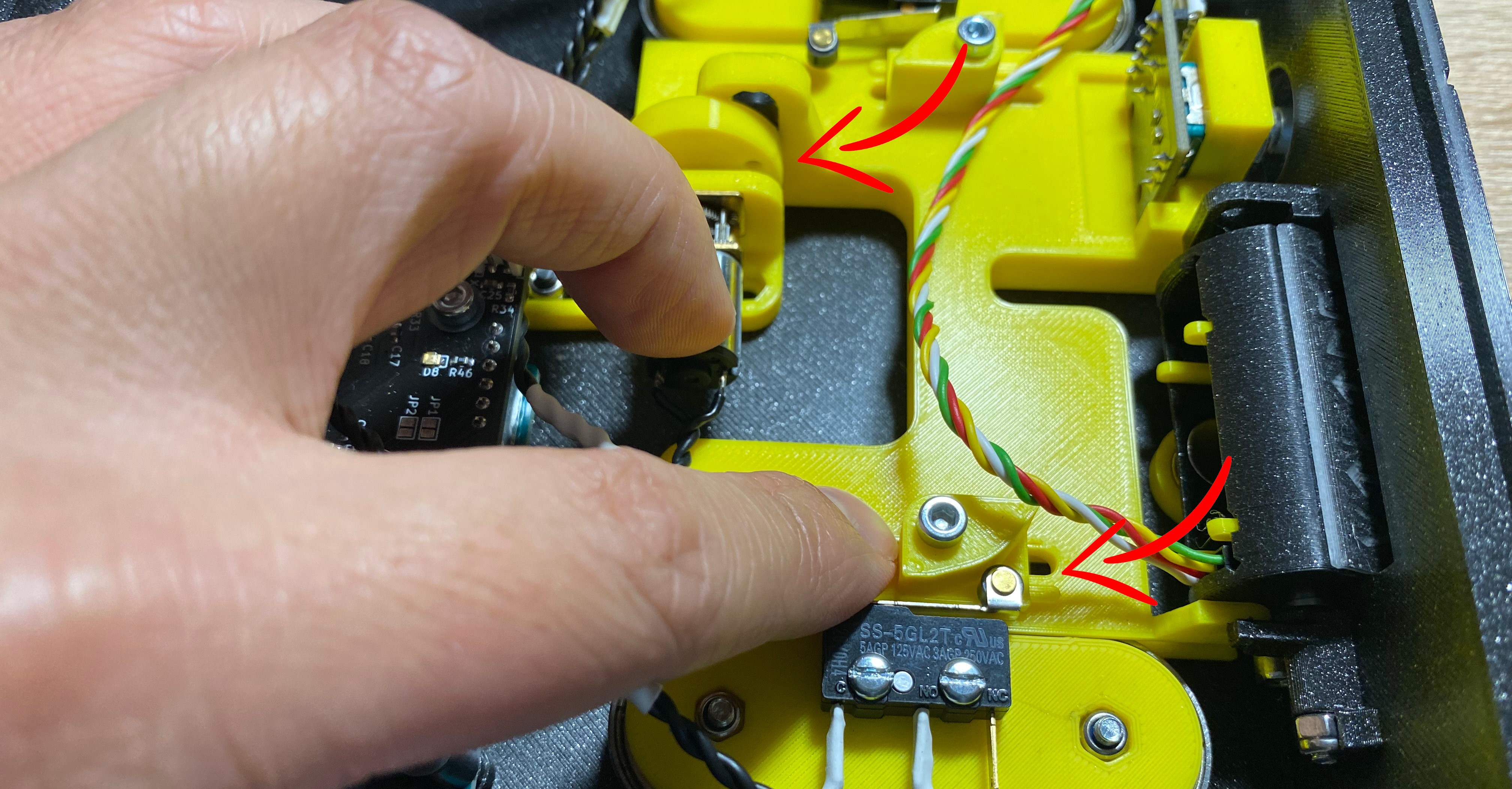
Step 49 - Adjust Front Endstop Knob
Adjust Front Endstop Knob
Slowly rotate the eccentric shaft to the front position.
Adjust the front endstop knob position. It has to just click when the mechanism arrives to the front position.
Tighten the screw to fix the knob.
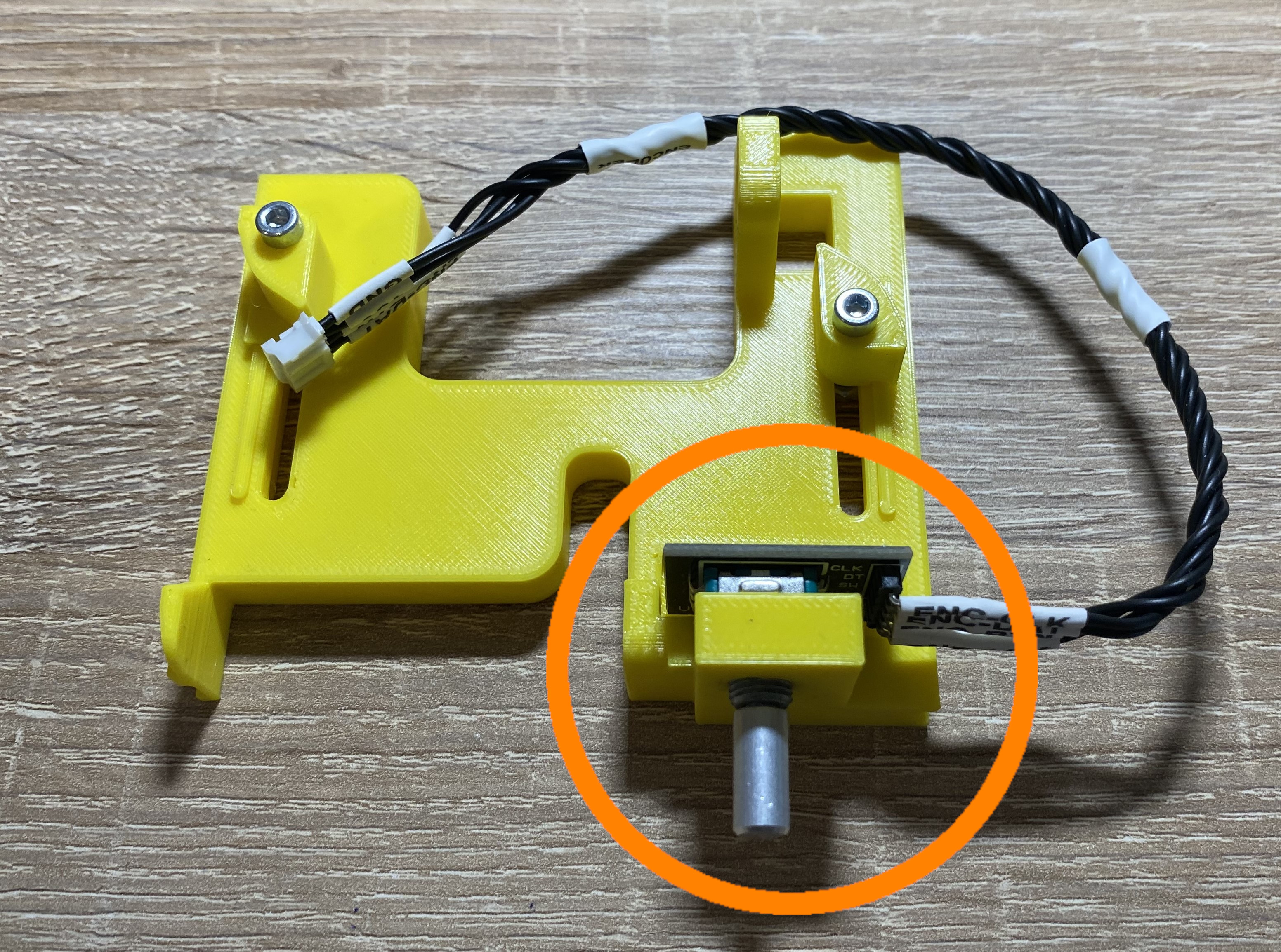
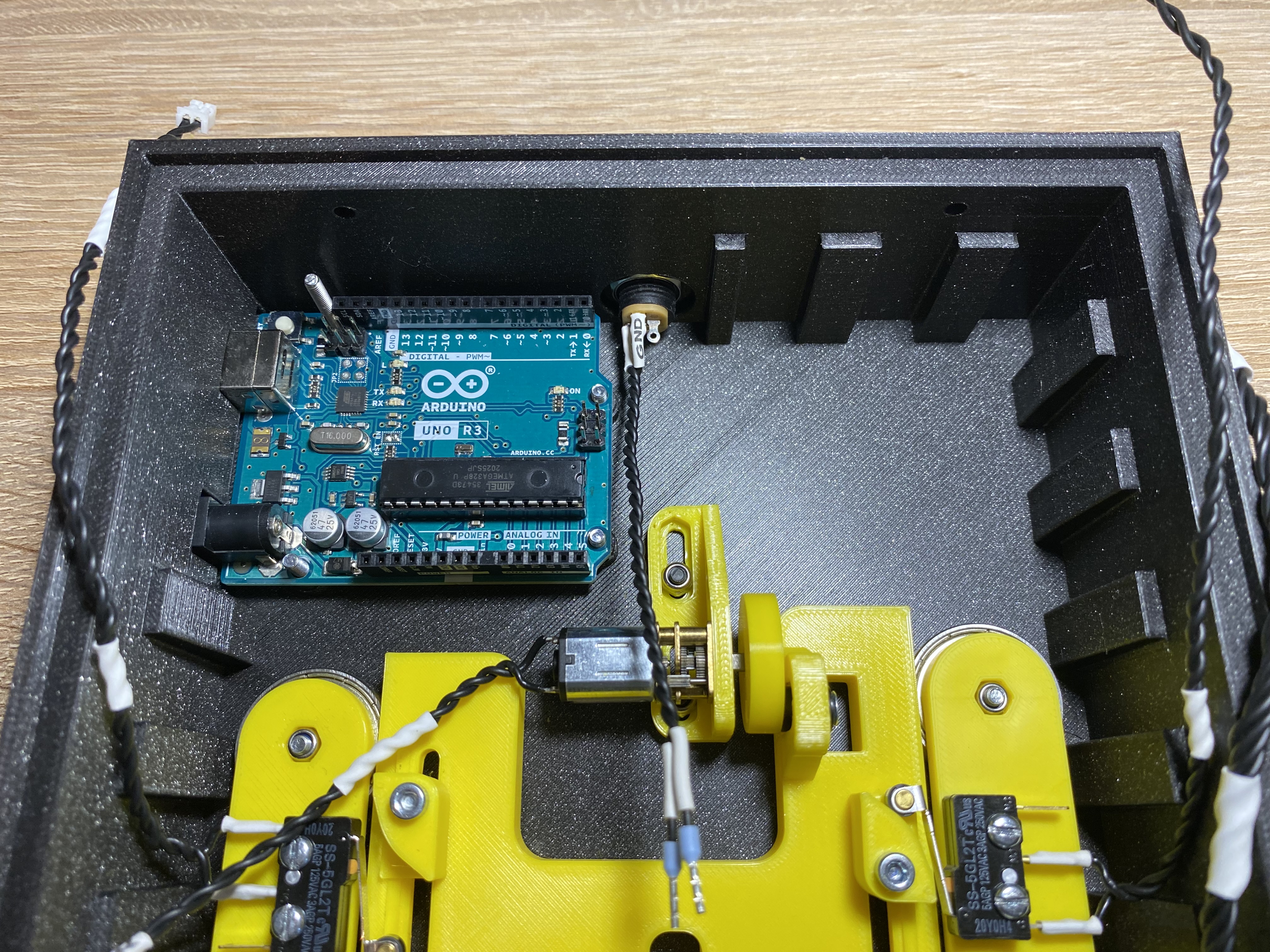
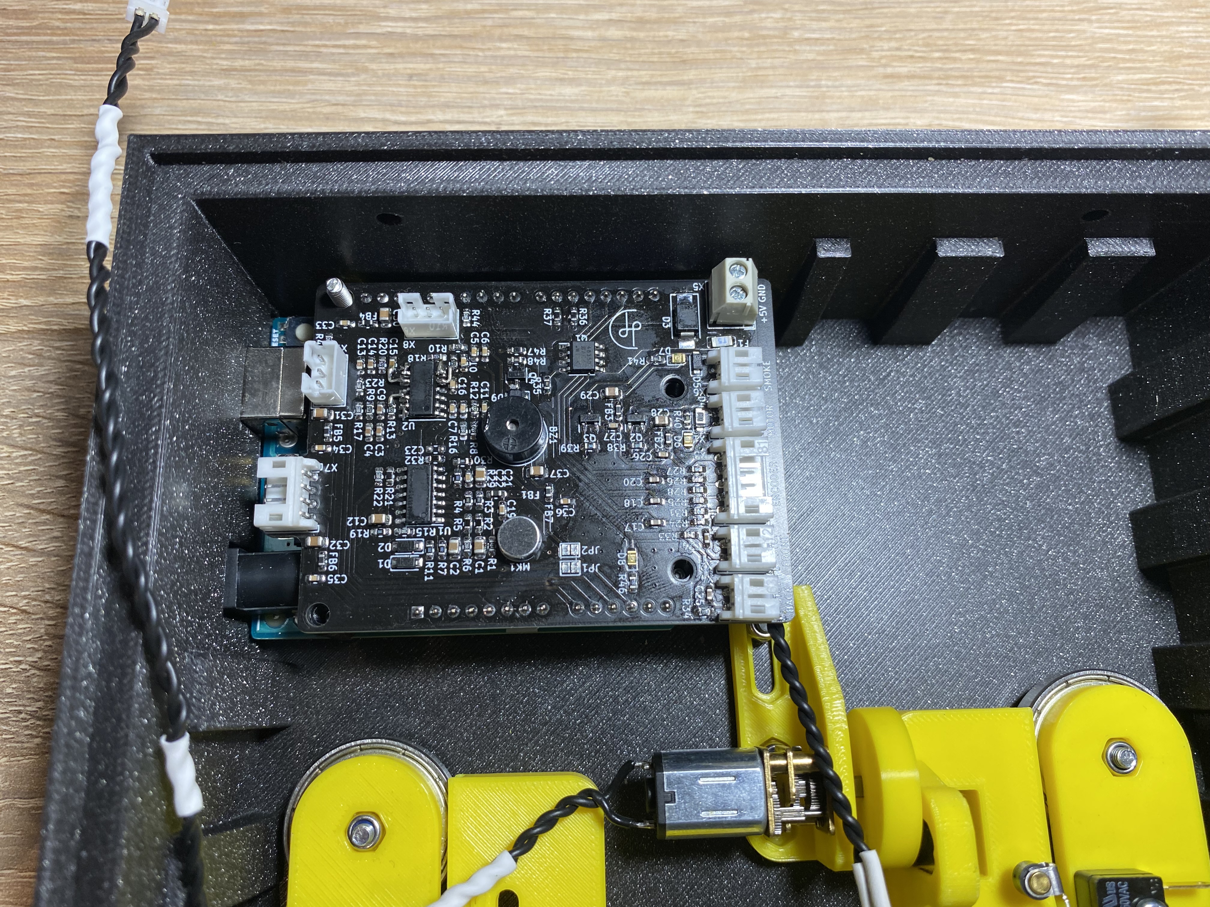
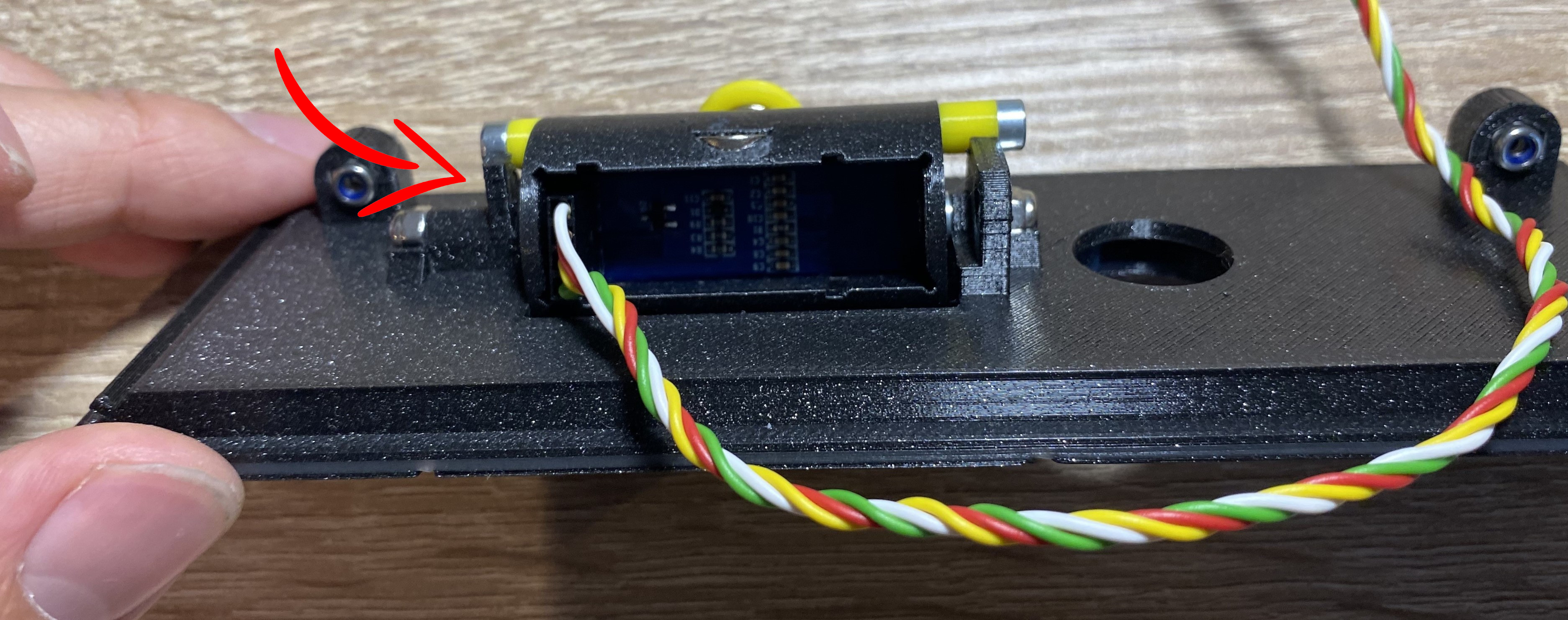
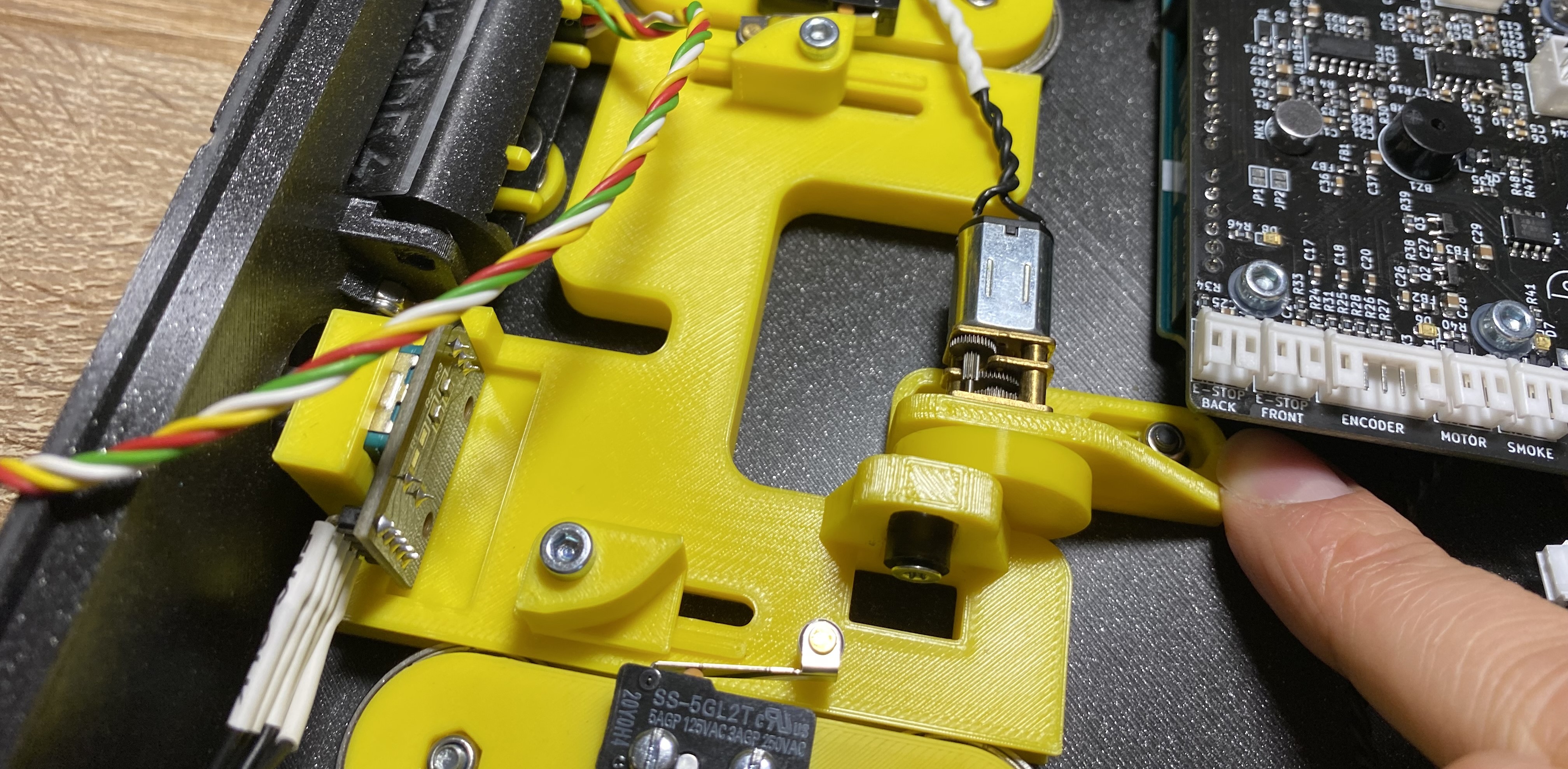
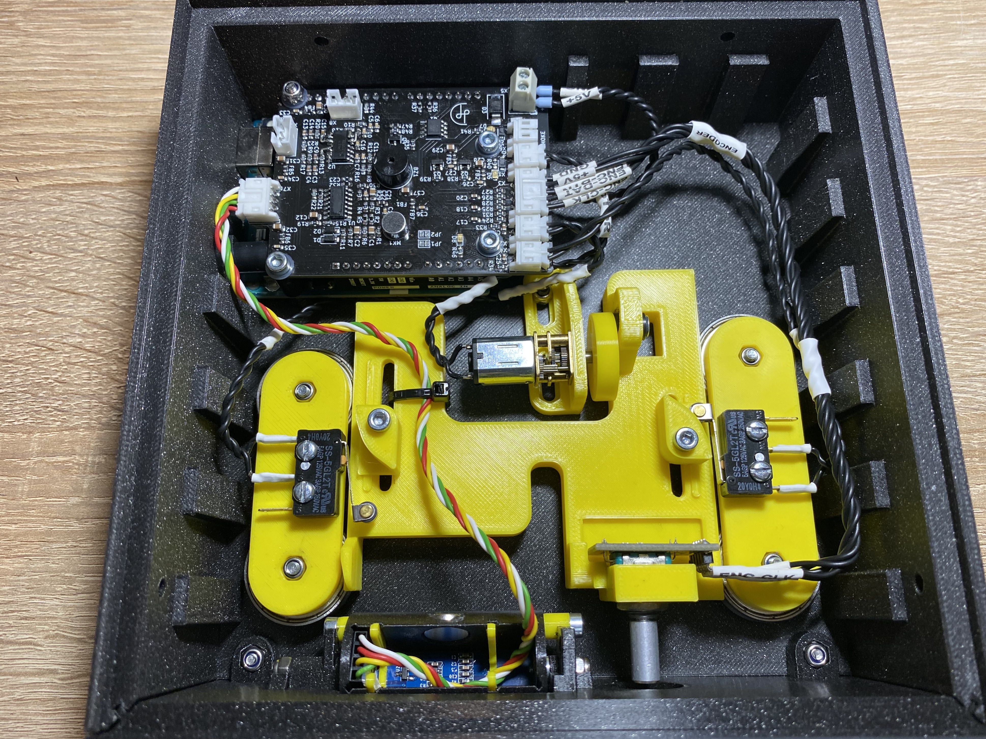
Step 50 - Connect Wires
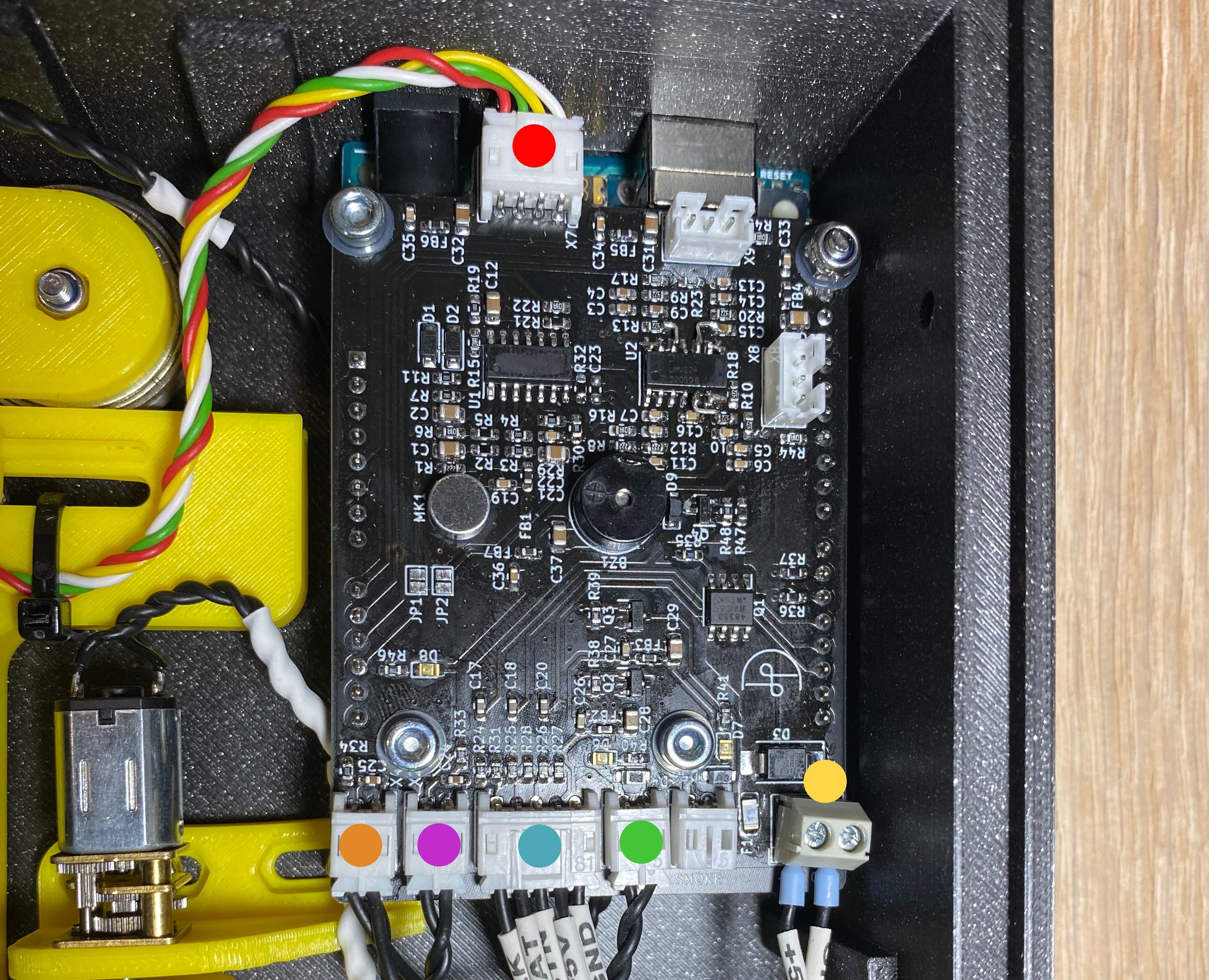
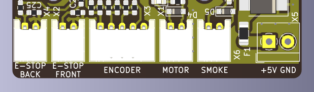
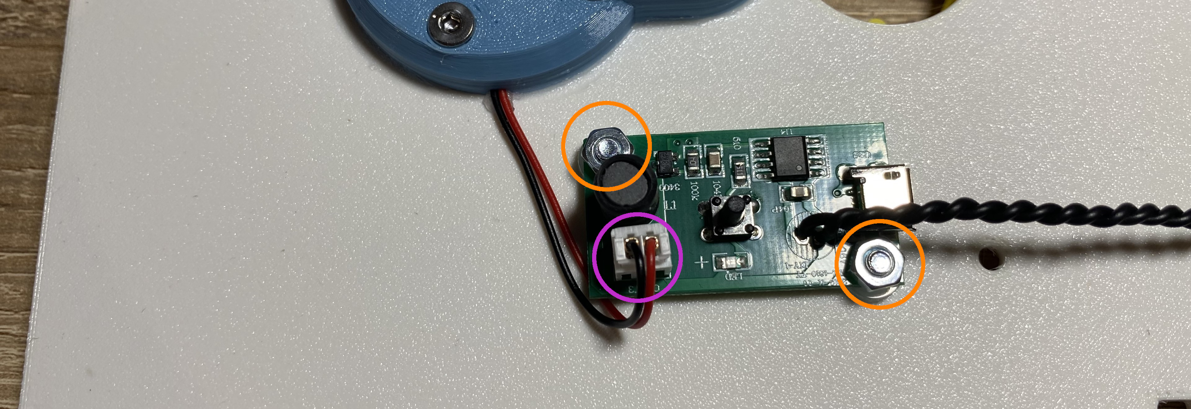
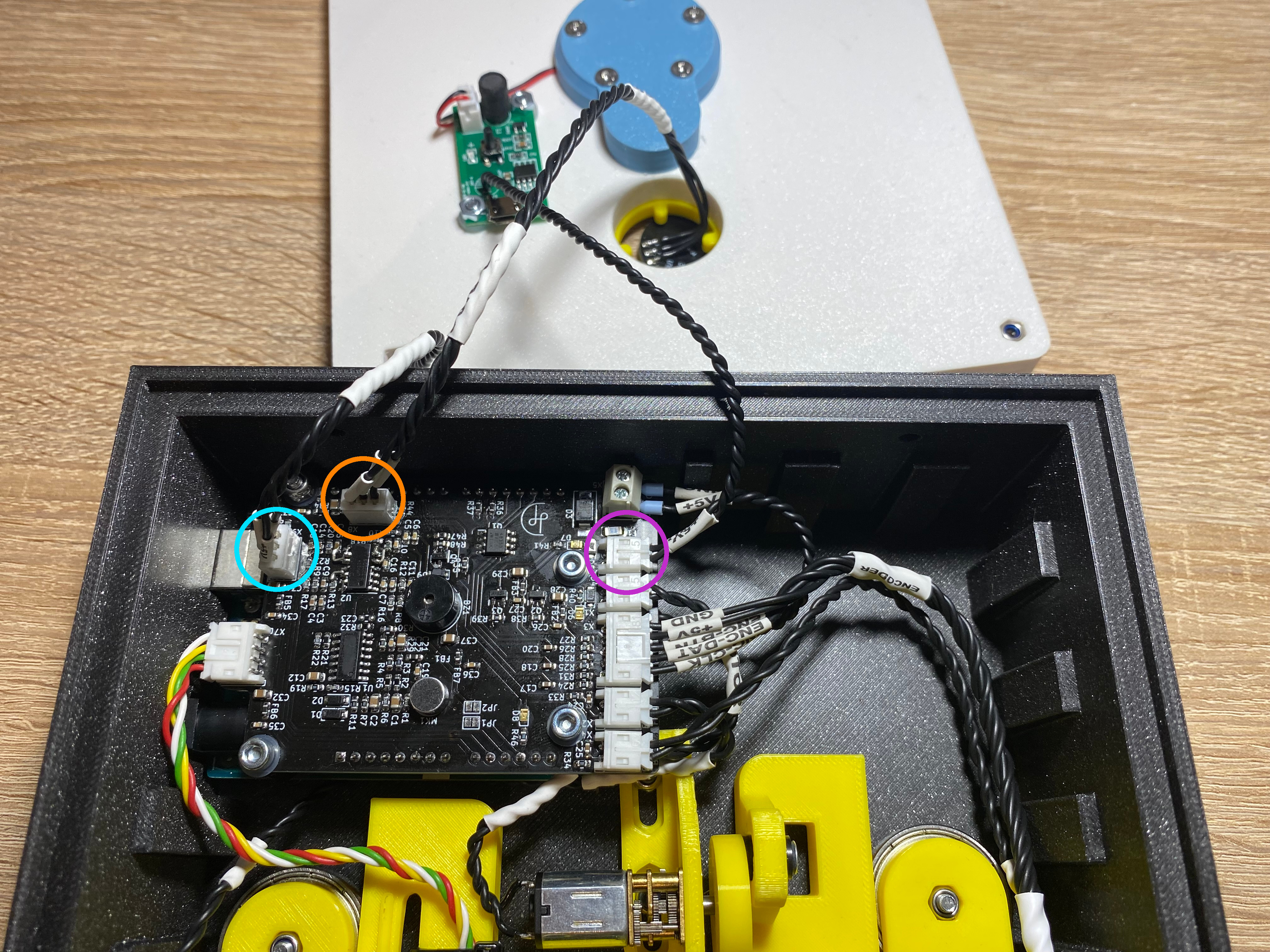
Connect Wires
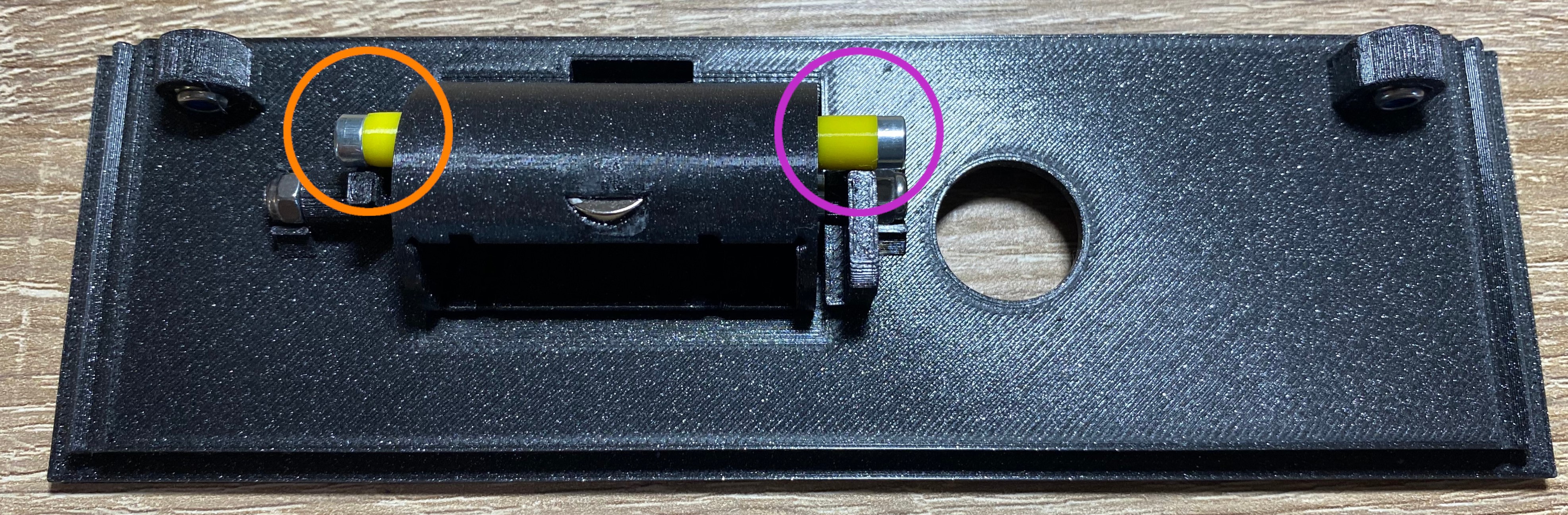
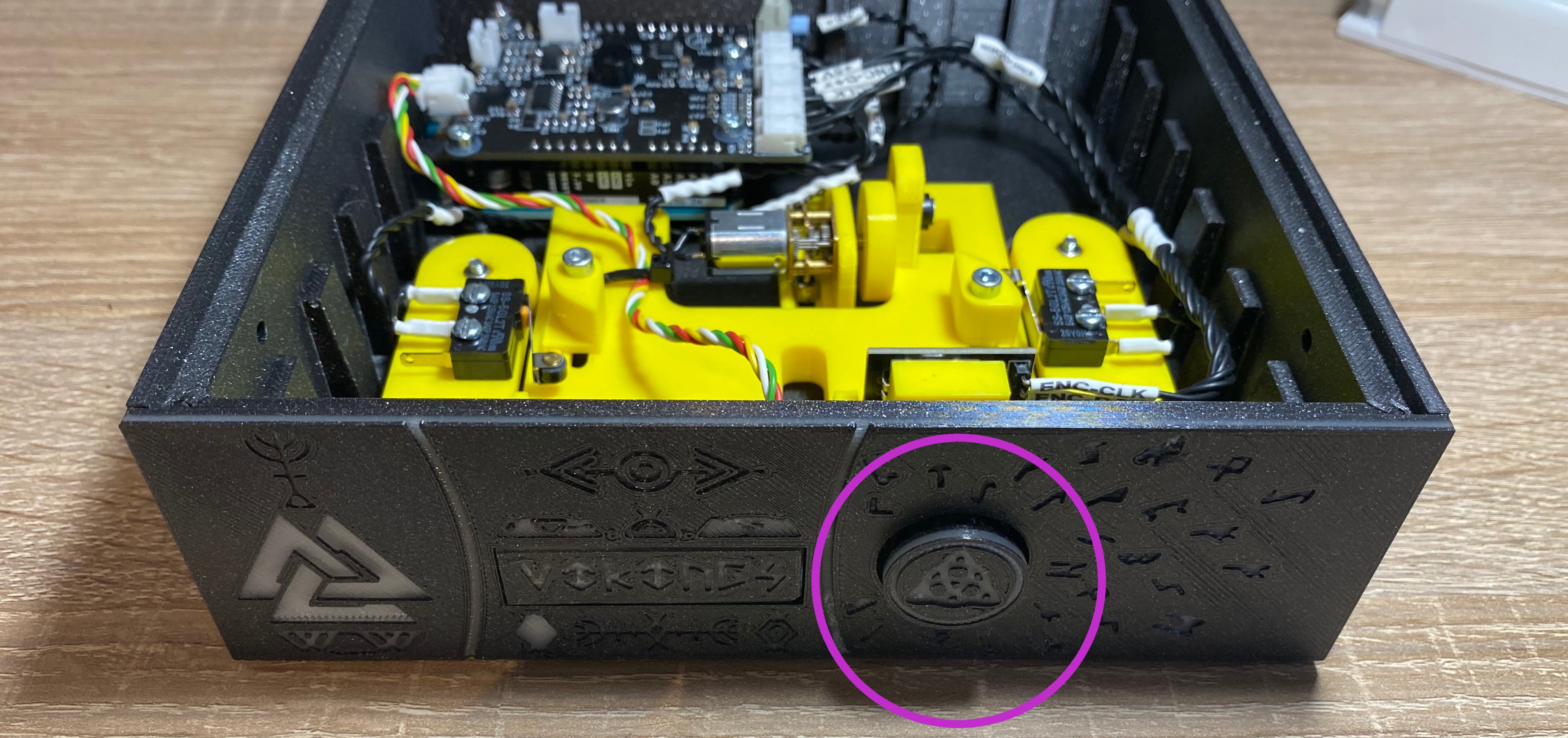
Pinout
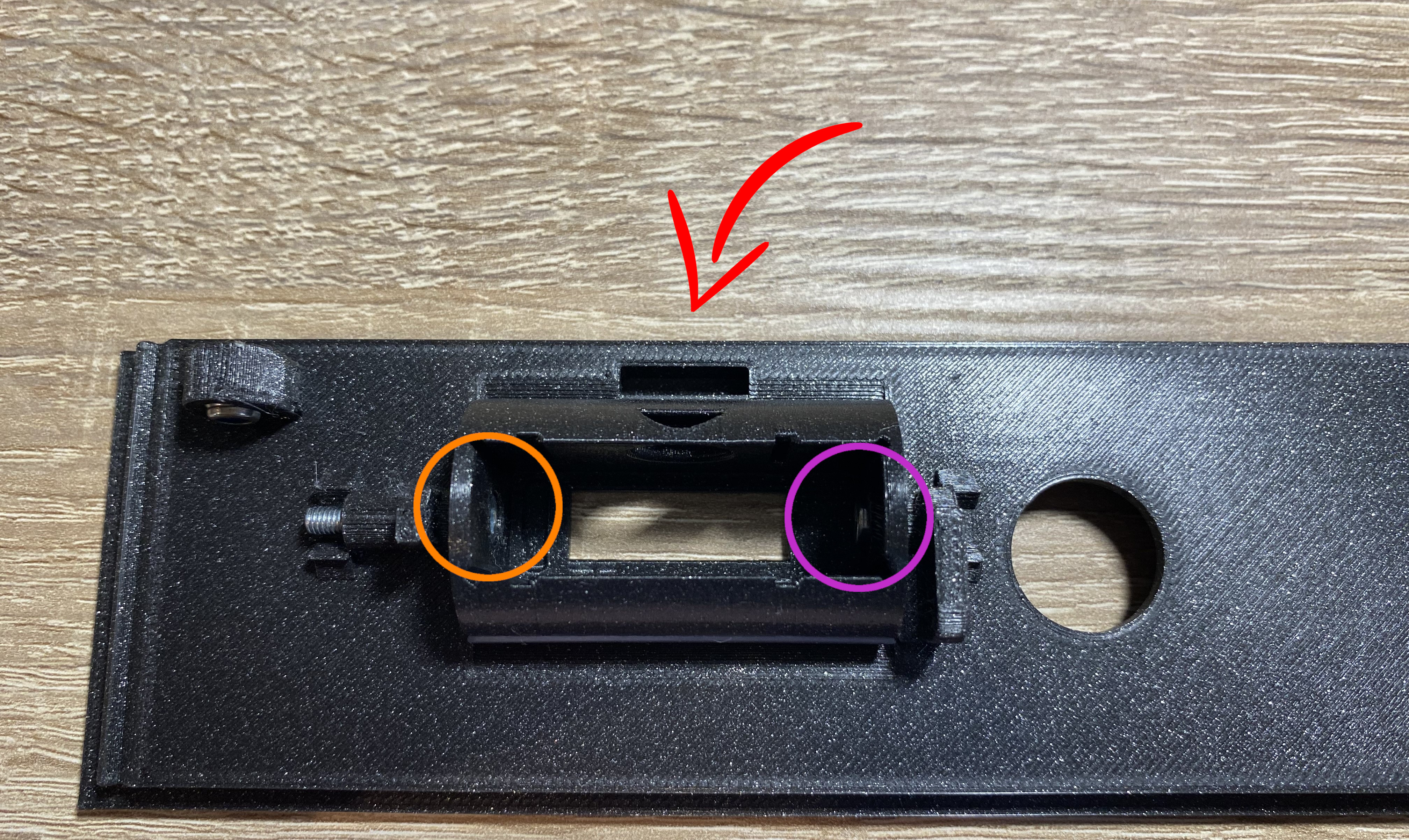
🟠 Back endstop
🟣 Front endstop
🔵 Encoder
🟢 Motor
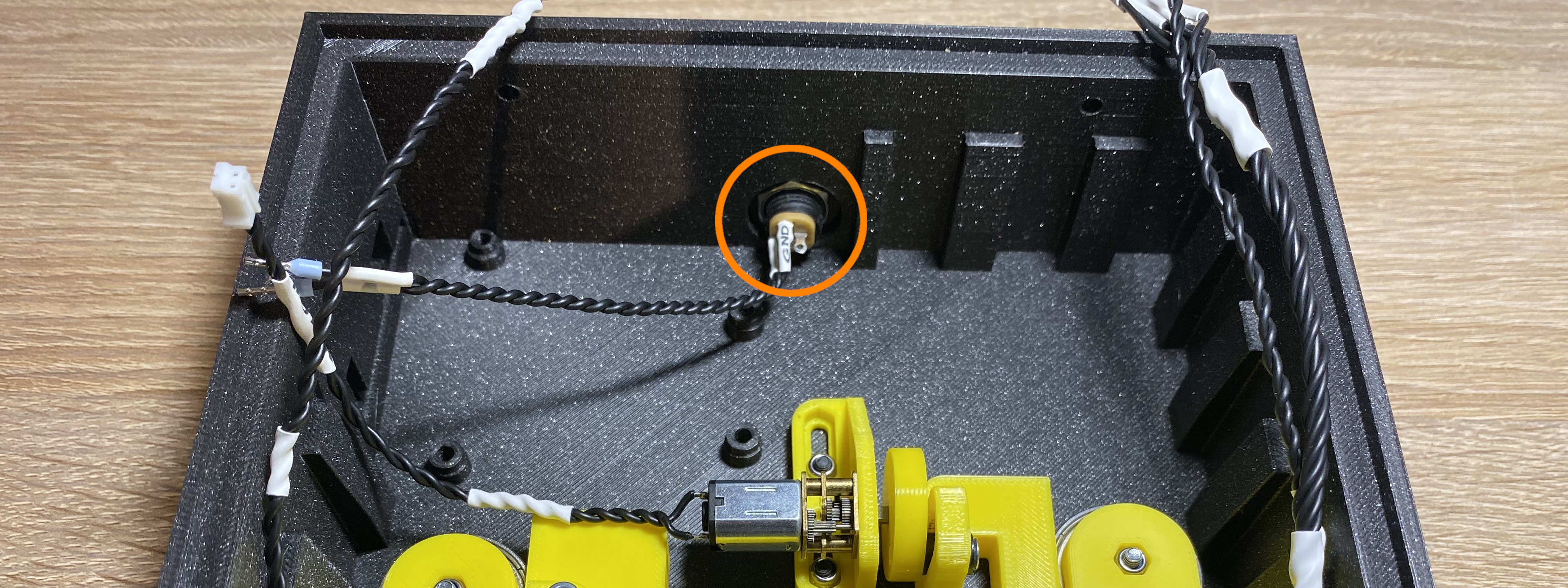
🟡 Input power ⚠Check the polarity!
🔴 Oled display.
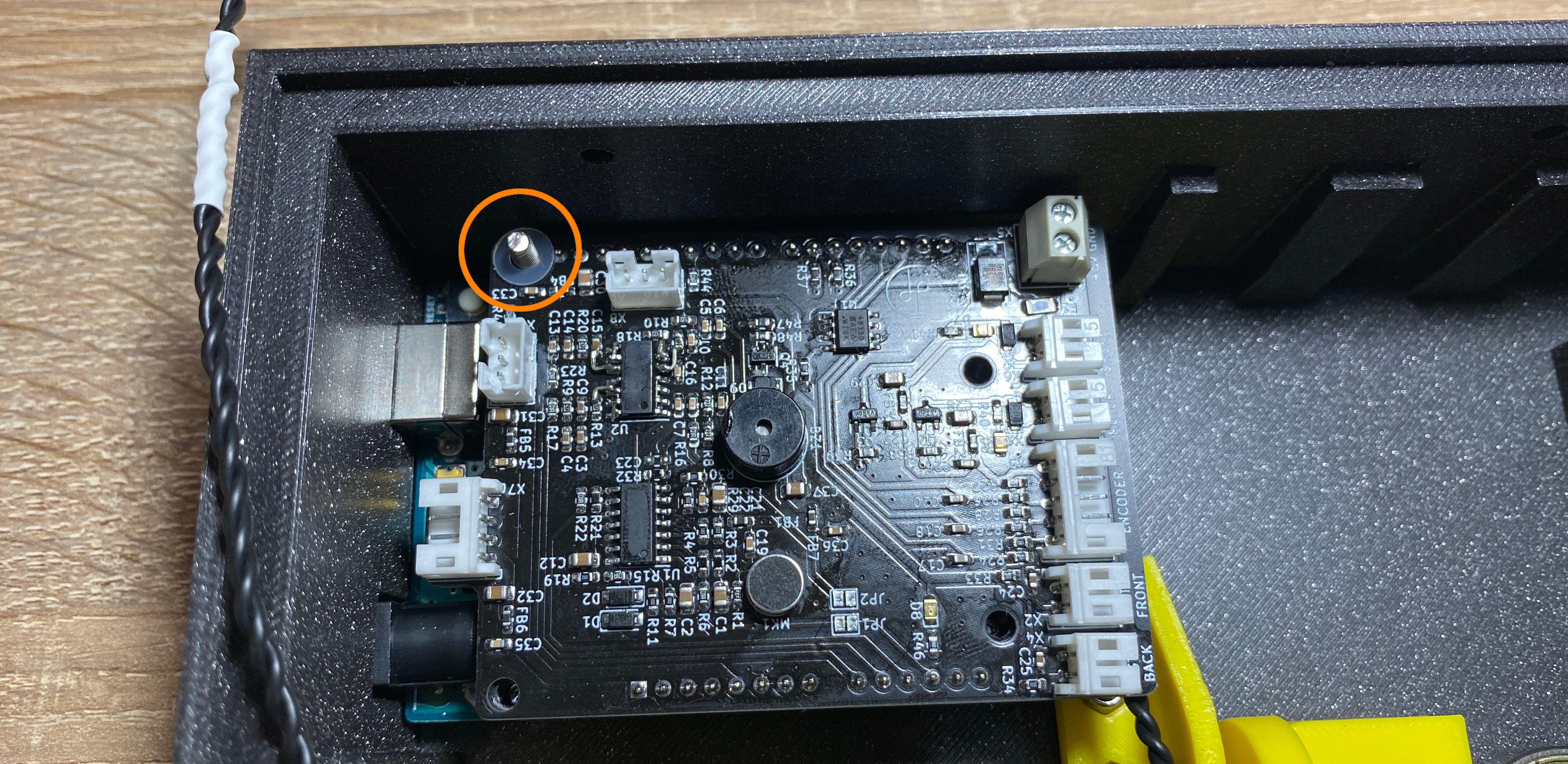
Note
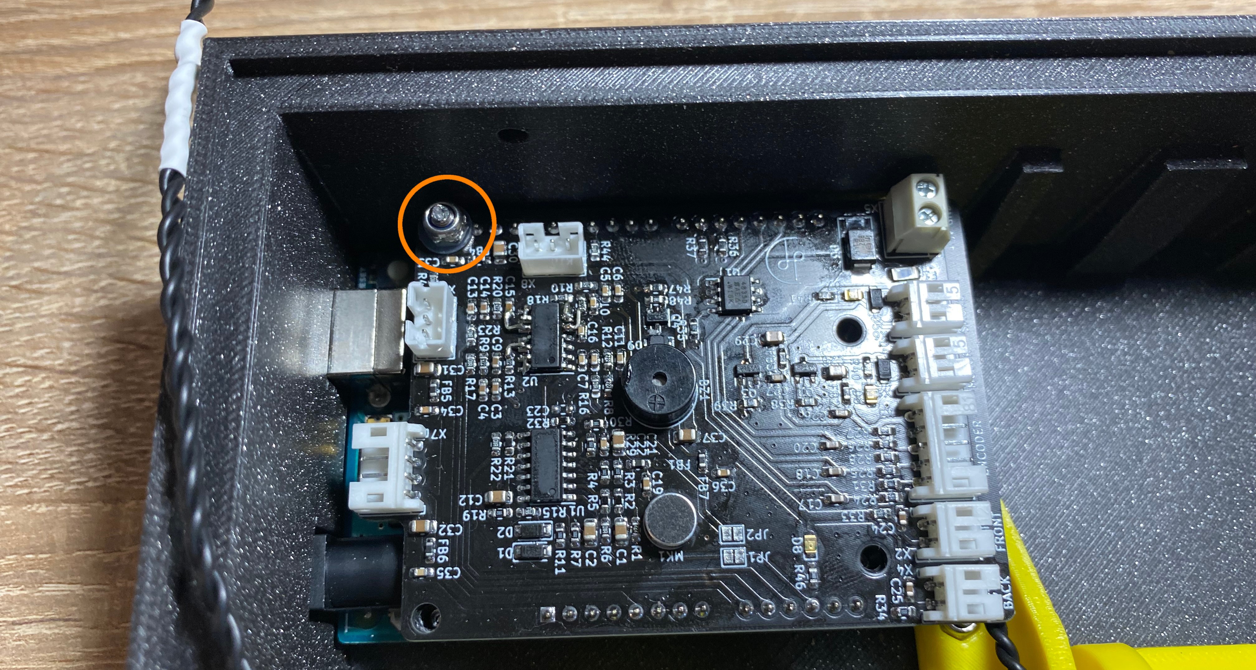
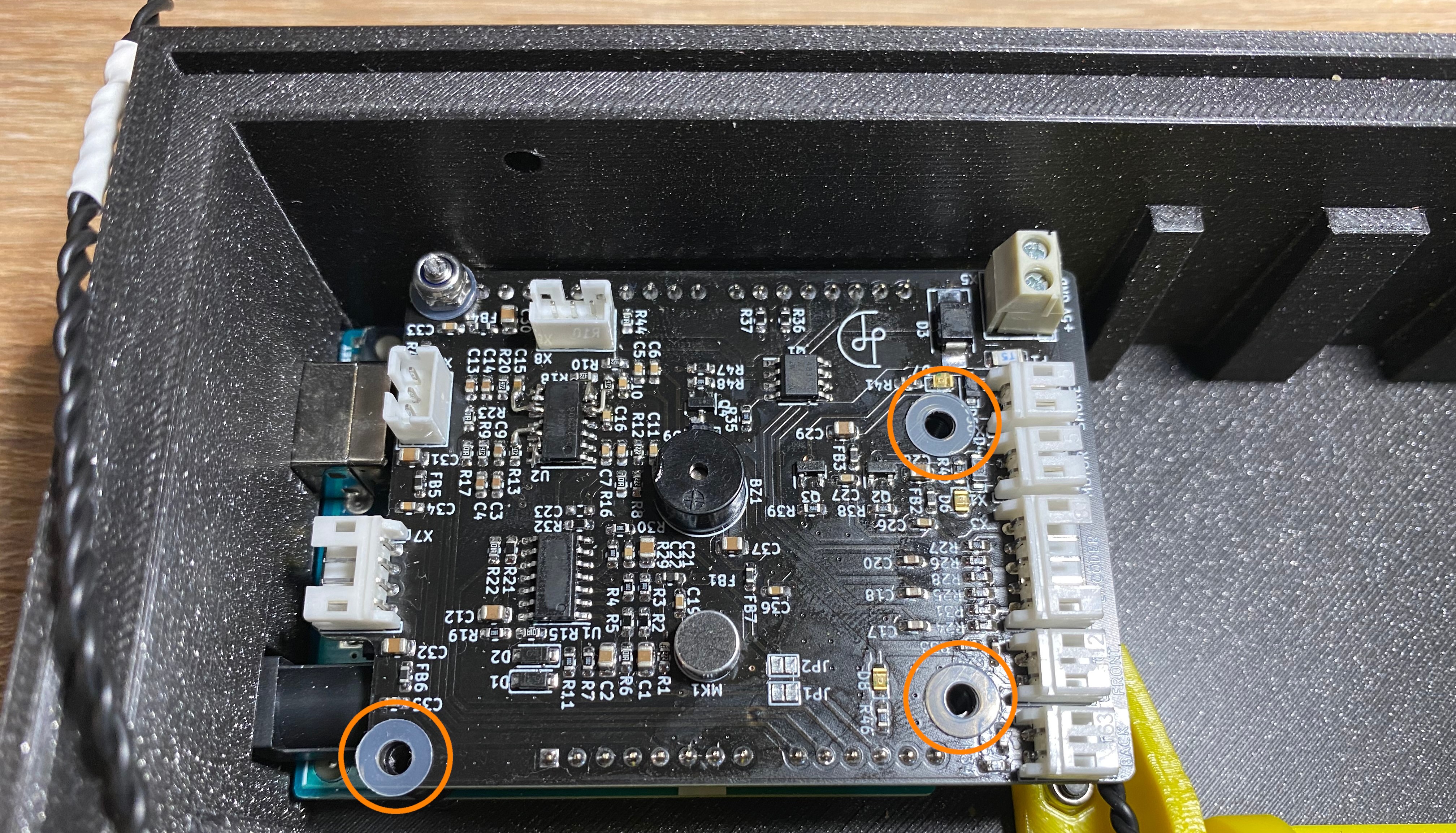
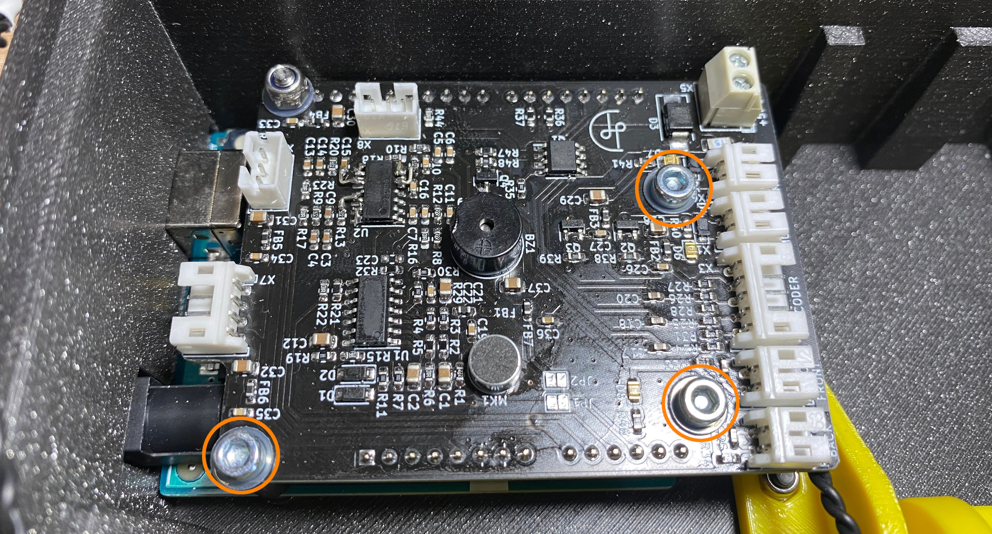
If the oled display cable won't fit easily, it is recommended to unscrew the Techno Viking PCB to access the oled display cable connector. After the display cable connected the PCB put back to it's place.
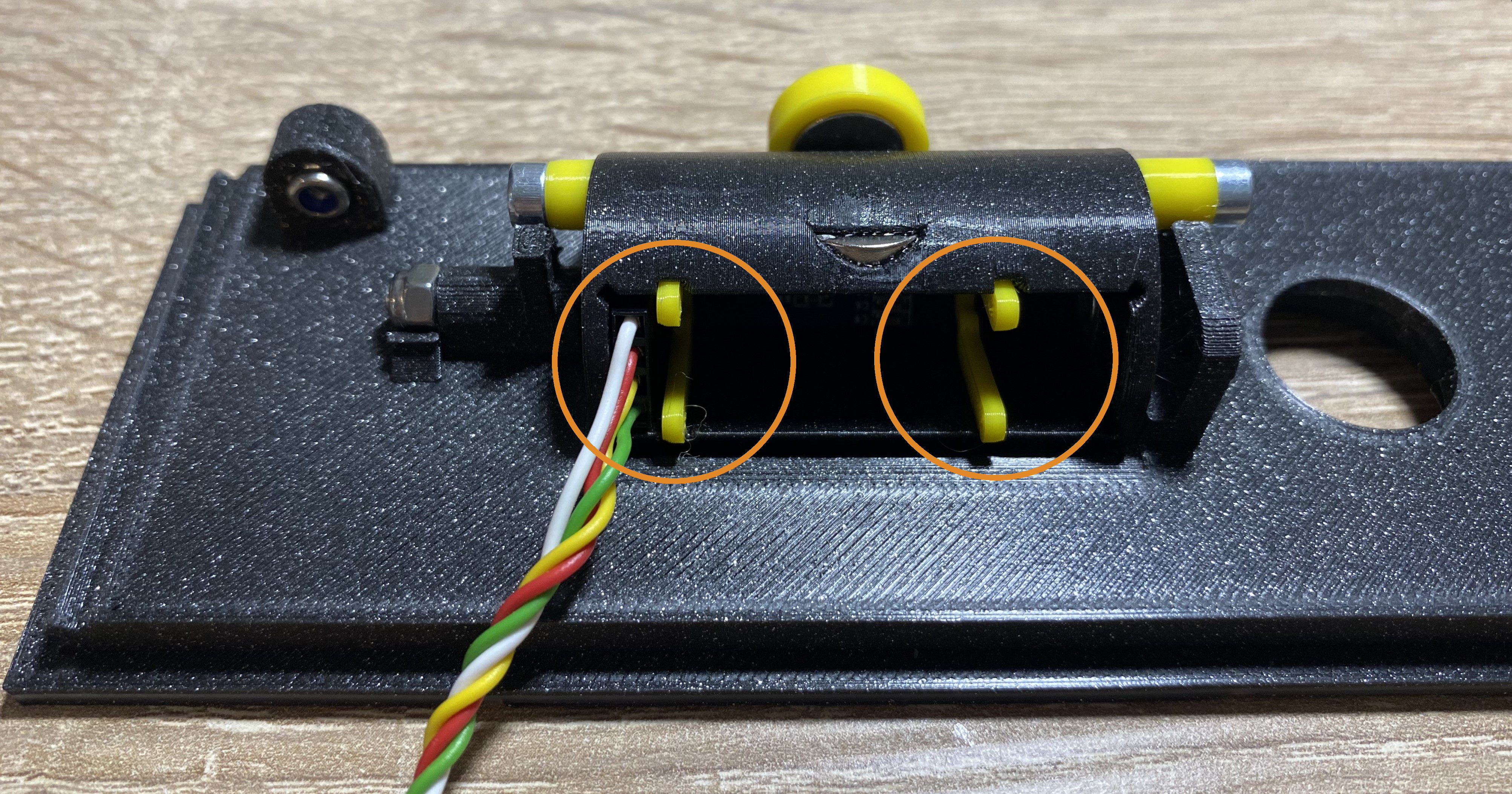
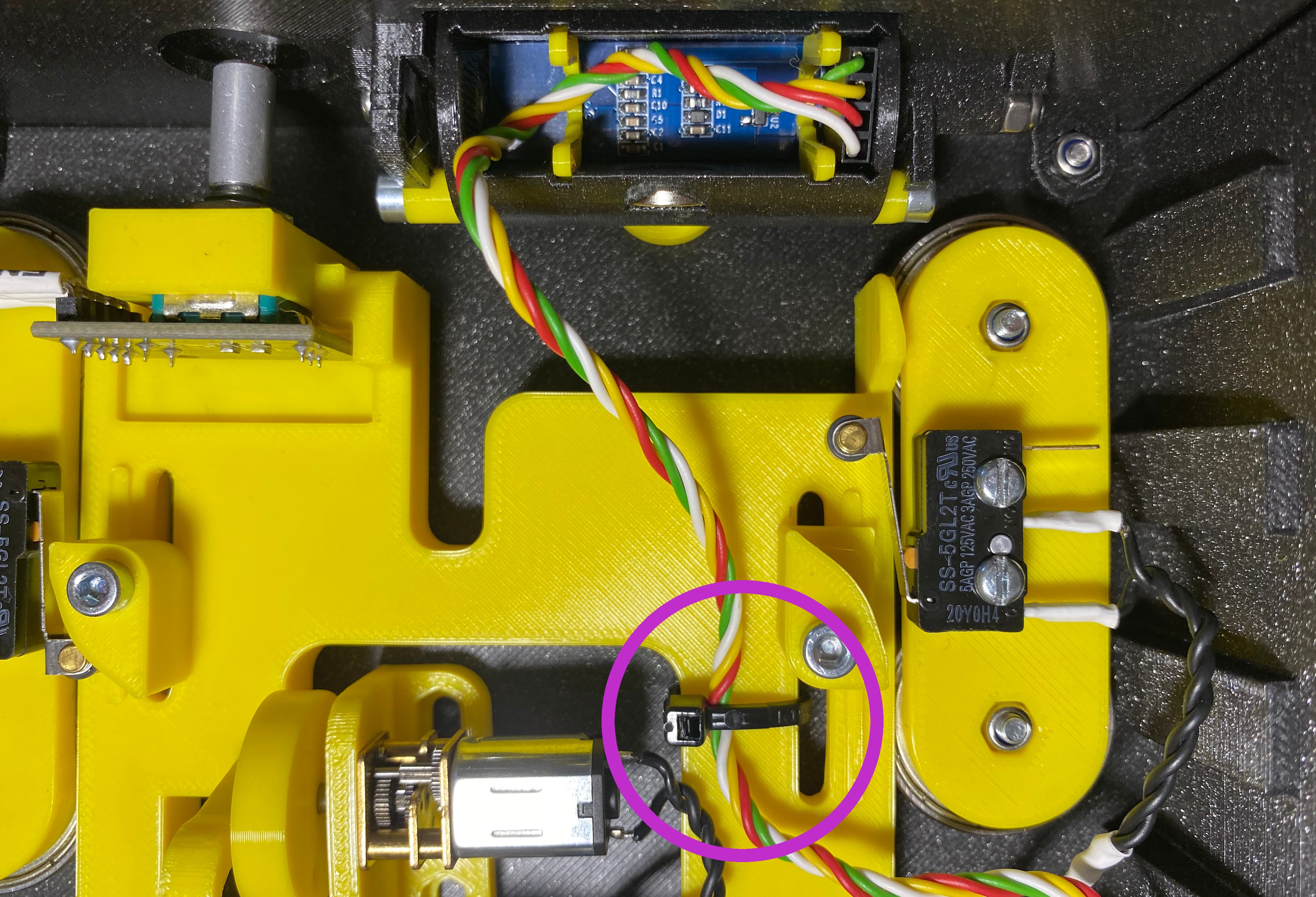
Step 51 - Oled Cable Tie
Oled Cable Tie
Secure the display cable with a cable tie.
Note
Make shore that the cable have enough room to move back and forward after it has been tied.
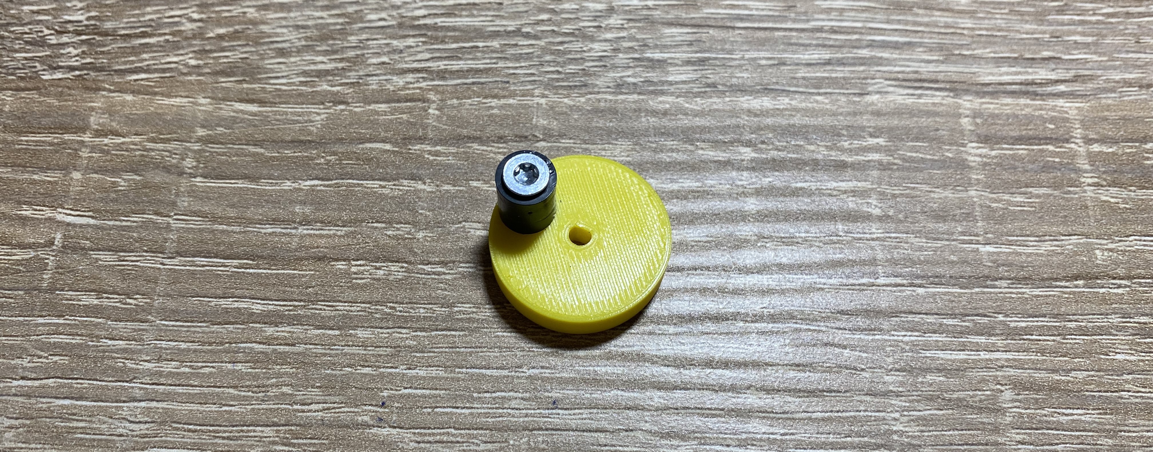
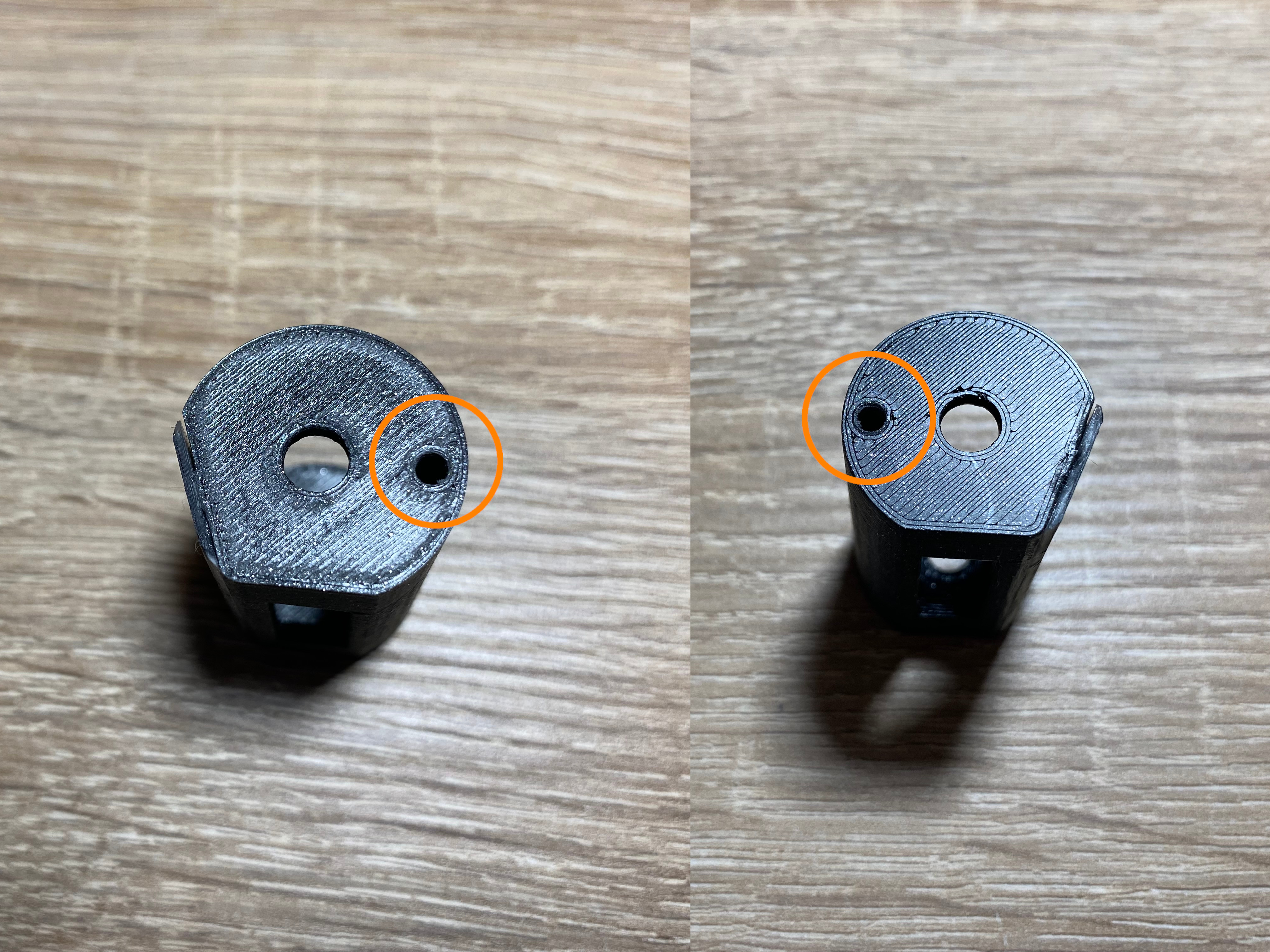
The encoder knob model is designed to fit multiple length encoder shafts. Maybe it can be pushed further than it should. In this case, insert some cotton swabs into the hole in the knob until it's internal length is perfect.
Step 53 - Upload Software
Now it's time to upload the software to the board. After it finished you can check the functionality of the mechanism by double pressing the encoder button. Also the display should work. Maybe some adjustment on the endstop knobs are required.
Warning
Do not continue until the mechanism and the display does not work correctly!
Note
If the motor is too aggressive and fast, that means you made better mechanism than me 🎉. In this case you have to lower the motor power by reducing the MOTOR_PWM parameter in the firmware. It requires to rebuild the software and upload it again.
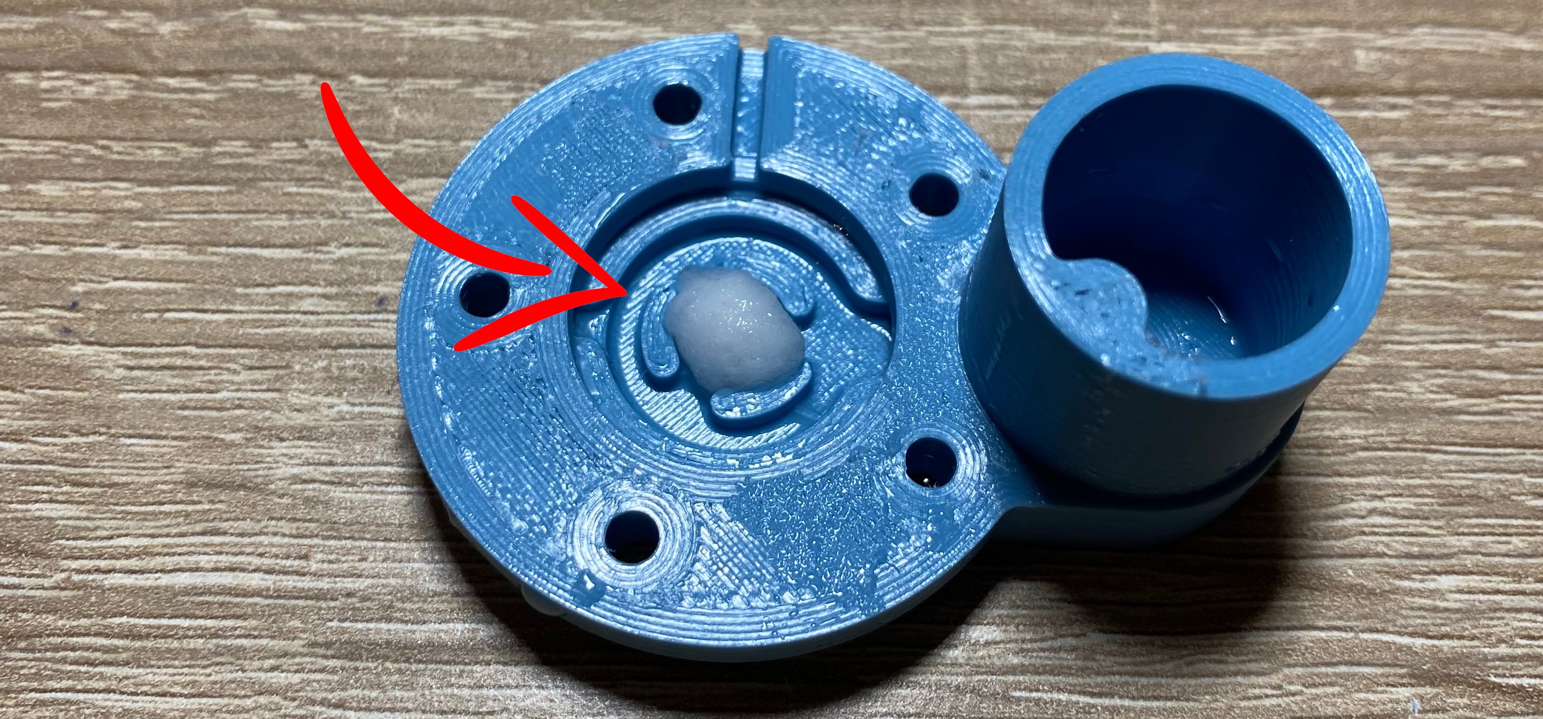
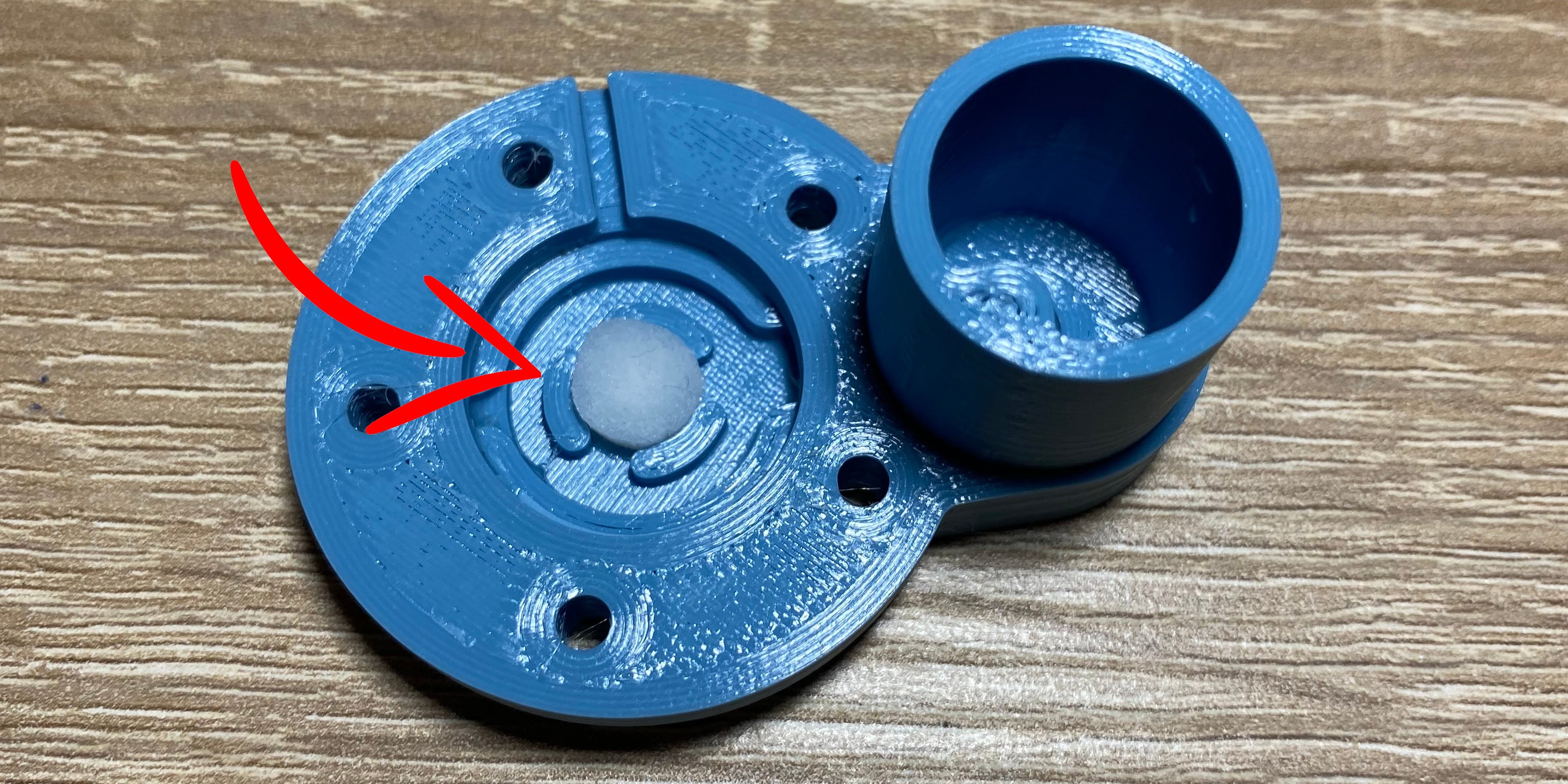
Some humidifier modules come with a cotton swab rod, some don't. If your does not contain it, you can use an ear cleaning stick, and use the cotton swab from it. If your module come with a cotton swab rod, you have to cut exactly 3mm long peace of it with an exacto knife.
Insert the cotton swab to the center slot on the atomizer socket.
Step 57 - Insert Atomizer
Insert Atomizer
Precondition
Required parts:
20mm Ceramic Humidifier Transducer With Silicone Housing - 1pcs
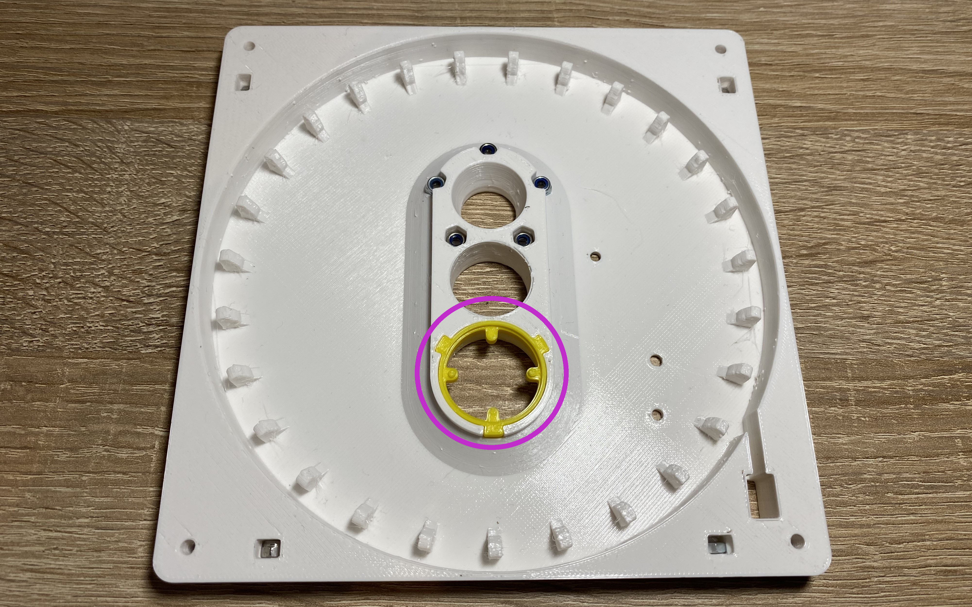
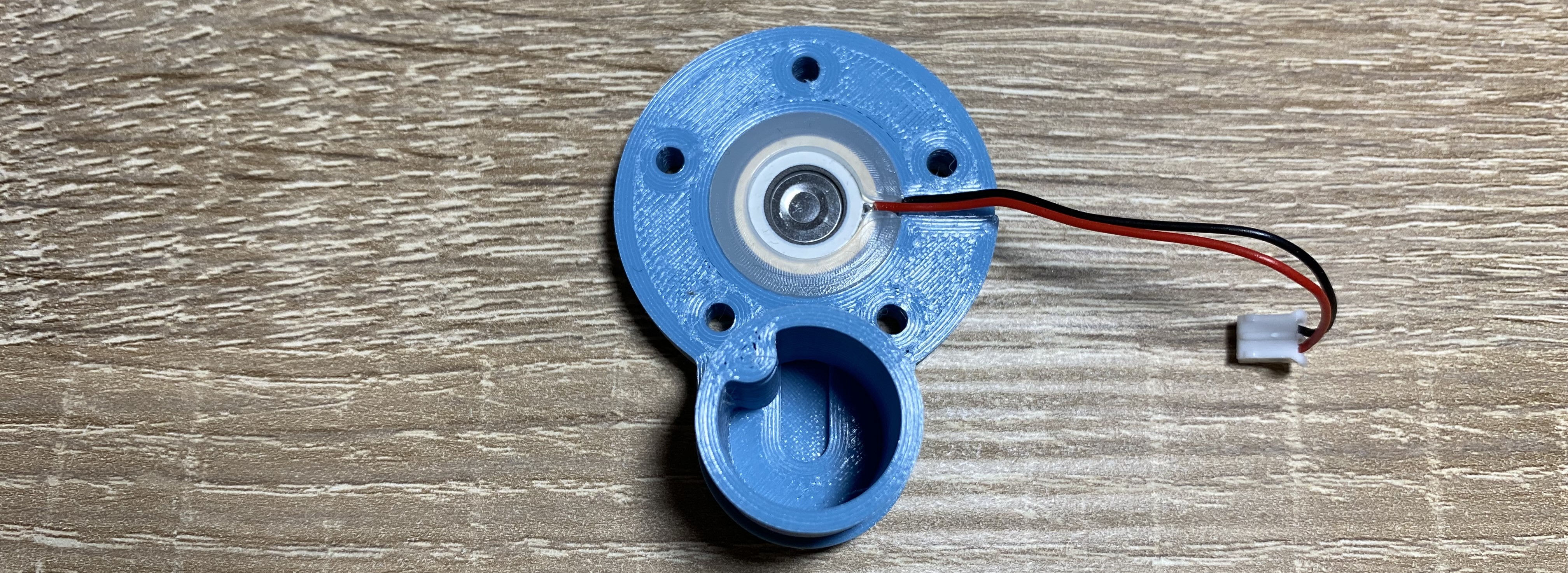
Insert the atomizer to the socket on the atomizer socket.
Note
Check the wire orientation. It has to slide into the slot on the atomizer socket.
Warning
Do NOT use any glue or sealant. It could clog the return path and the humidifier wont work. Trust me I have tried it...
Step 58 - Fix Atomizer Socket
Fix Atomizer Socket
Precondition
Required parts:
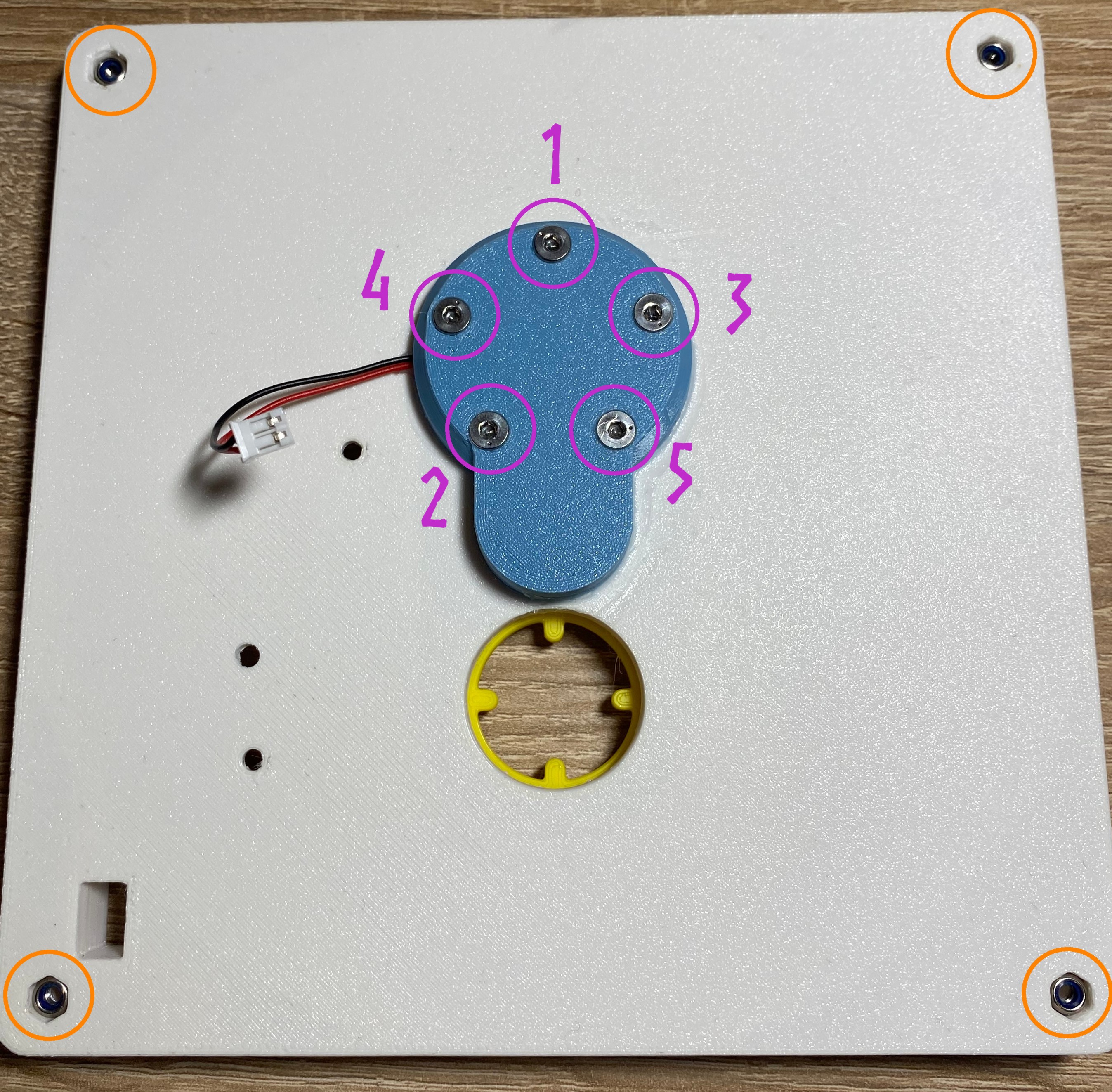
M3 x 20mm FHCS - 5pcs
M3 Lock Nut - 4pcs
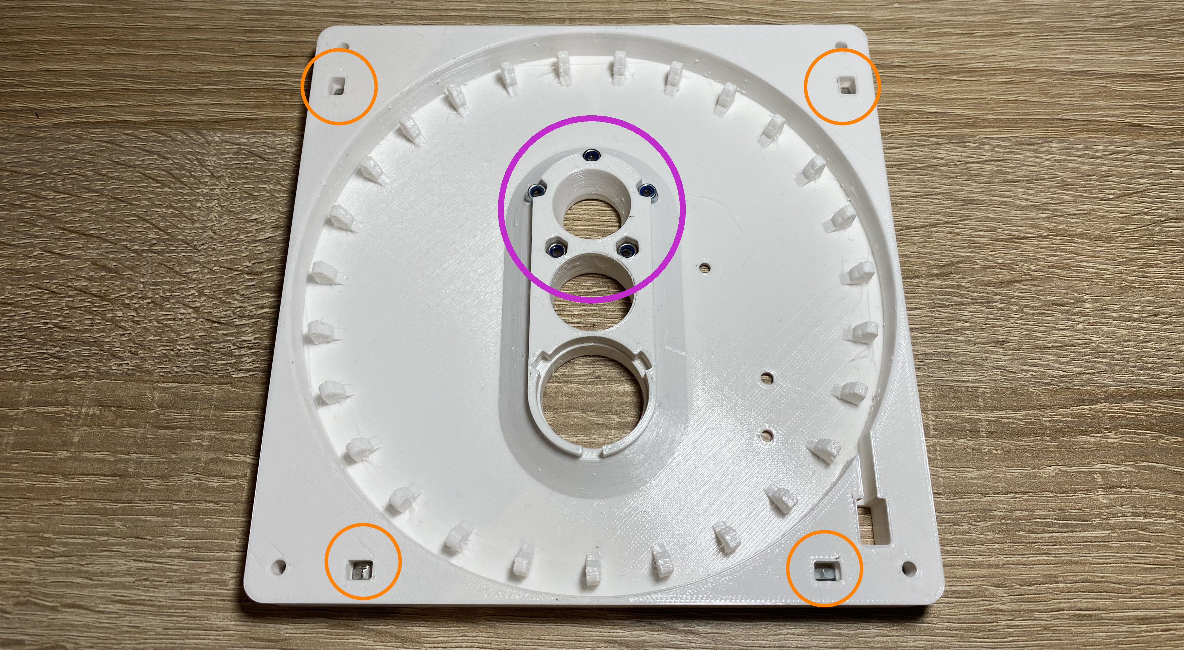
🟣 Tighten the screws using a star pattern. If it's too loose, it will leak.
🟠 Insert the nuts to the slots.
Note
Check the wire during the process. It can stuck between the two surfaces.
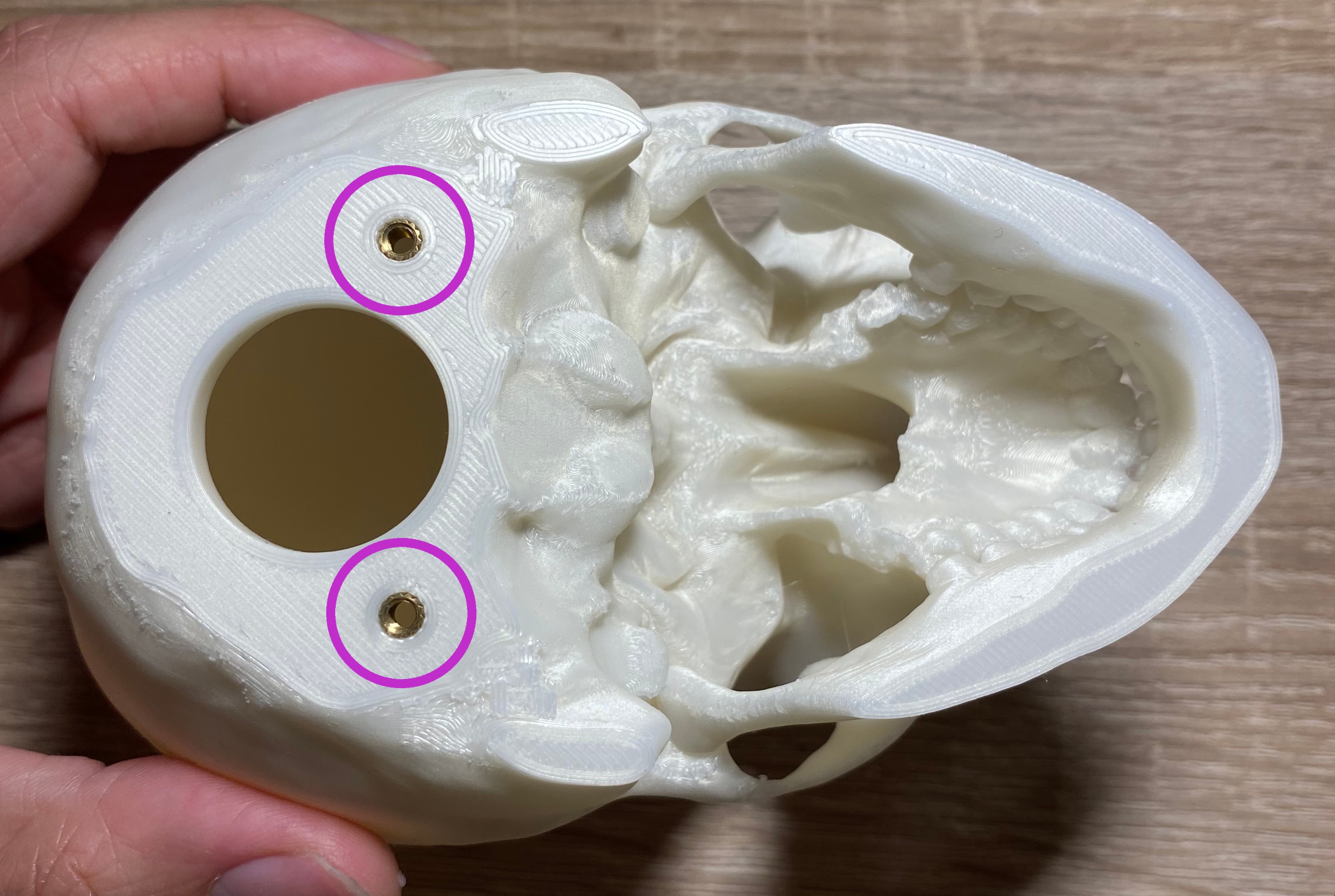
Step 59 - Humidifier PCB Holes
Precondition
Required parts:
3.2mm Drill Bit
I have bought a few humidifier module and the hole positions were different for each. If your modules hole positions are different, lock the board to one hole and drill another one. To fix the humidifier PCB, at least two screws are required.
Step 60 - Insert Humidifier PCB Screws
Insert Humidifier PCB Screws
Precondition
Required parts:
M3 x 8mm Imbus Head Screw - 2pcs
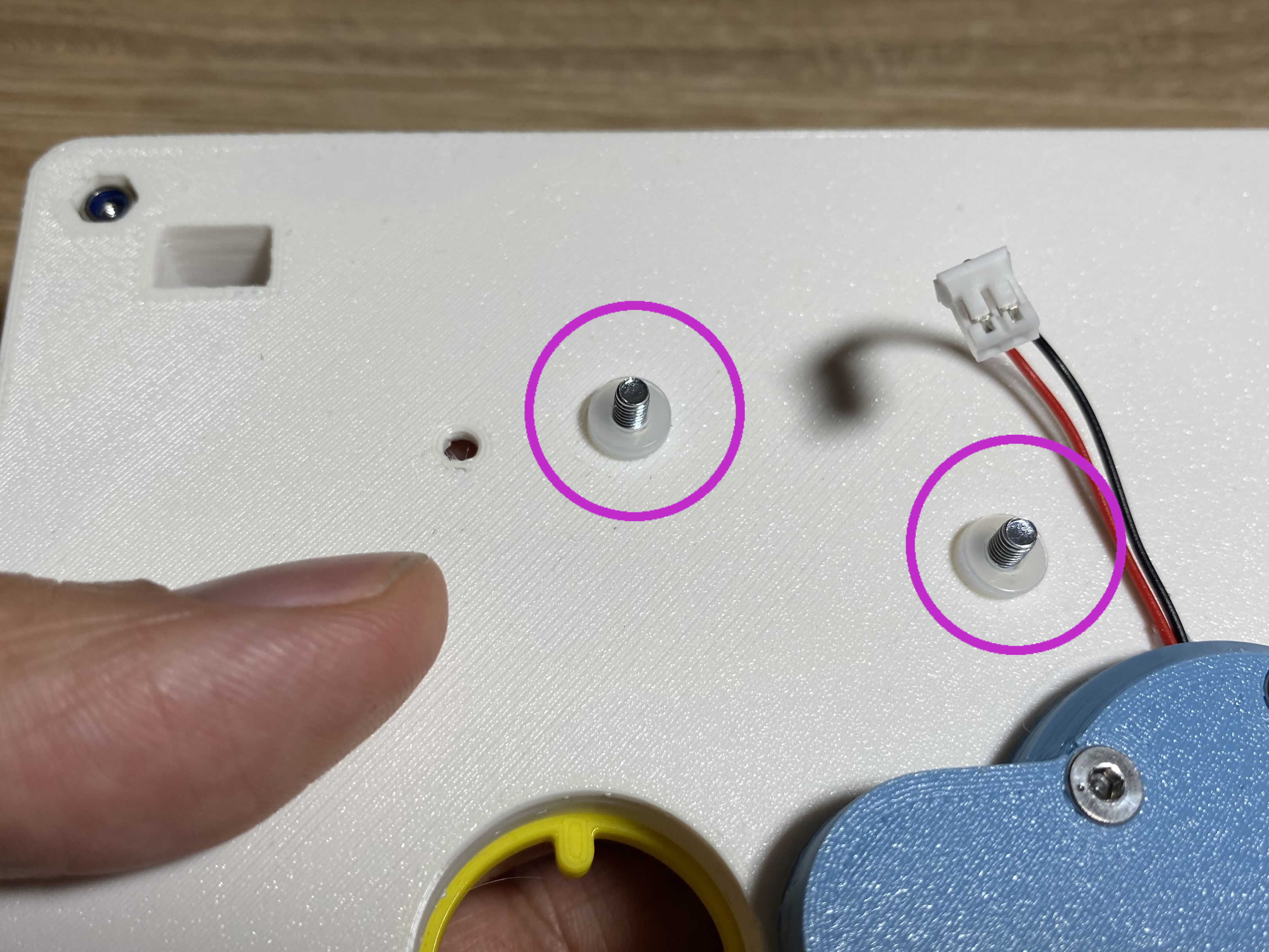
M3 x 0.5mm Plastic Spacer - 8pcs
1. Insert the two screws from the top.
2. Insert 4 - 4 plastic spacer to the screw from the bottom.
Step 61 - Fix Humidifier PCB
Fix Humidifier PCB
Precondition
Required parts:
M3 Regular Nut - 2pcs
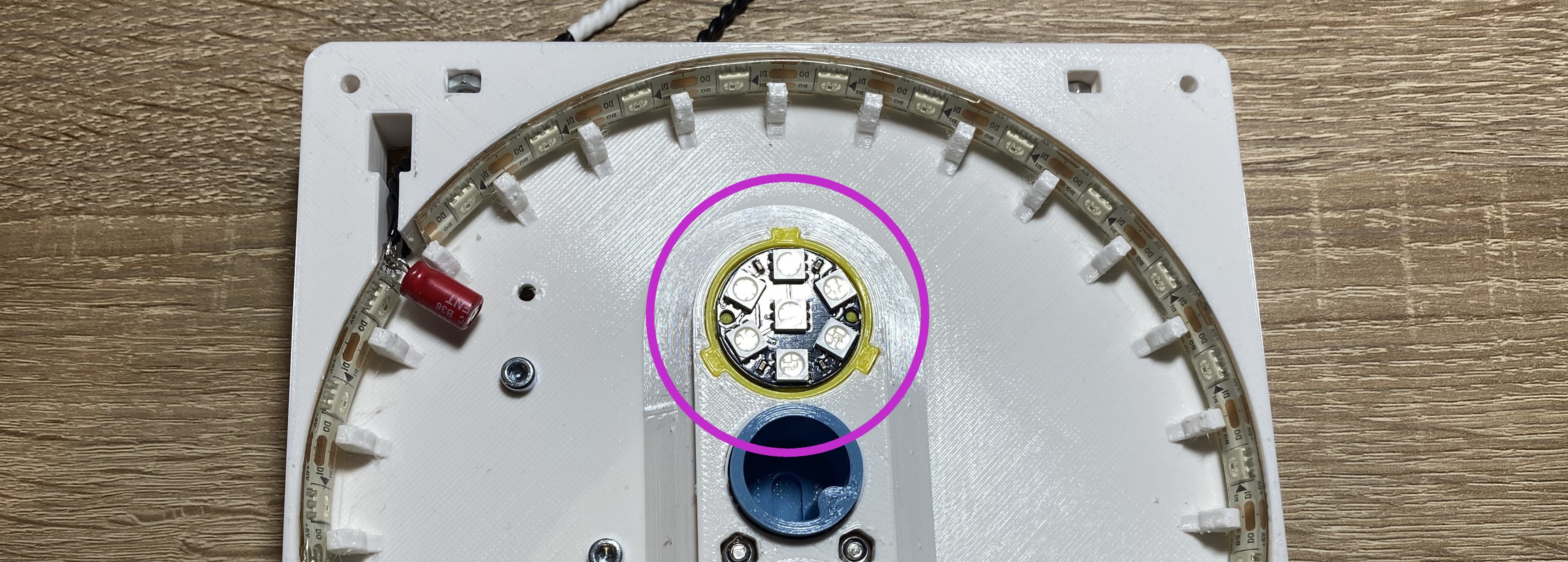
🟠 Tighten the screws.
🟣 Connect the humidifier disc cable to the PCB.
Step 62 - Humidifier Test
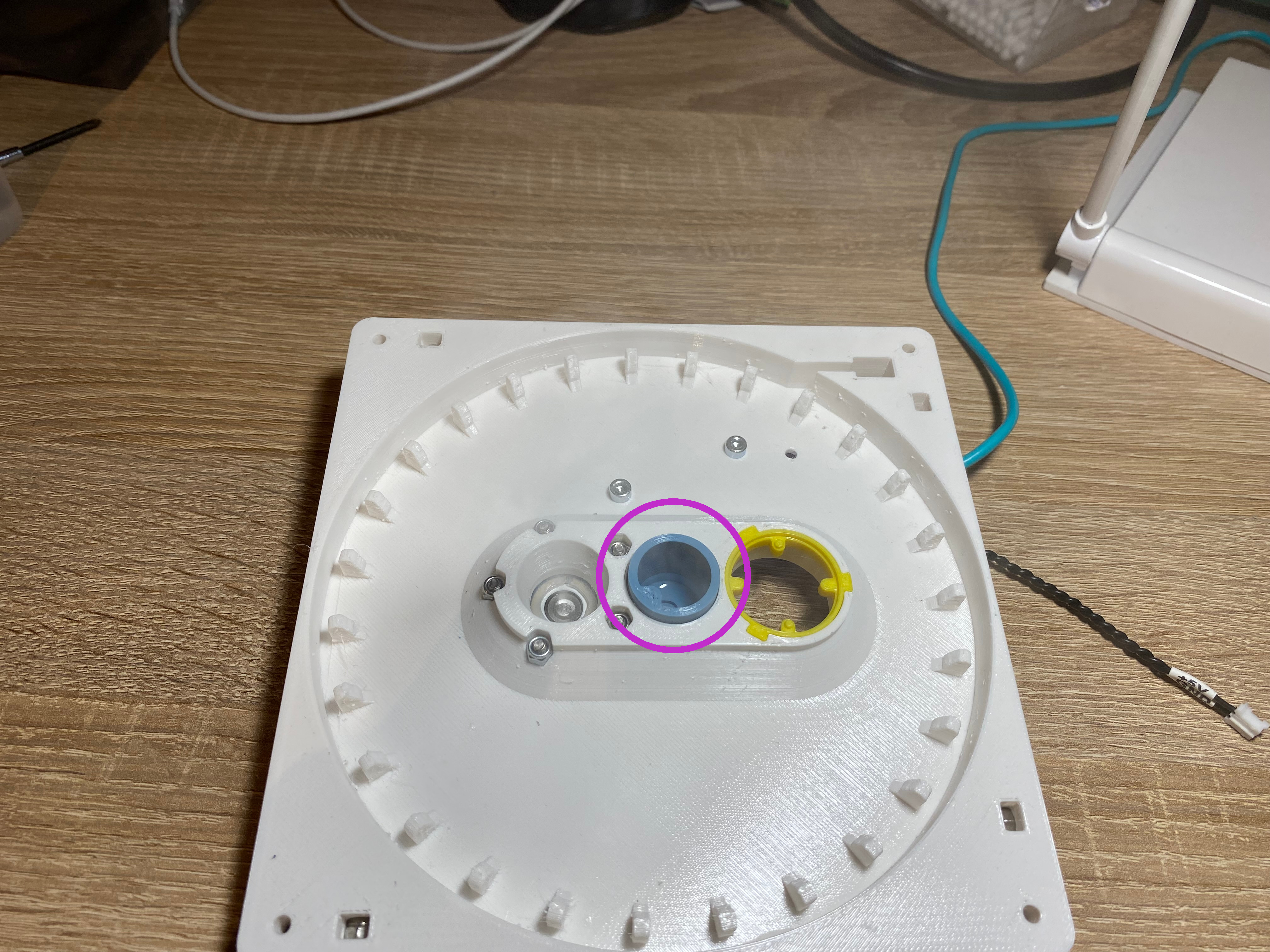
1. You have to make shore that the humidifier does not leak.
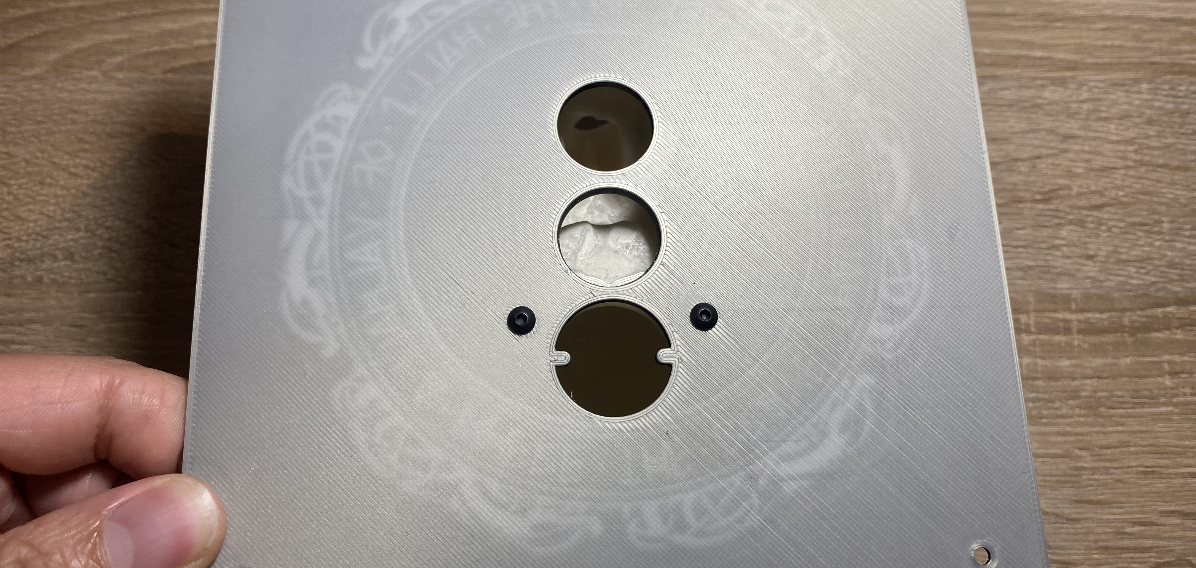
Fill The Tank
Fill the tank ( marked purple ) with a bit of water. Do not overfill it! It usually takes a few minutes to soak the cotton swab, please wait at least 5 minutes. If the cotton swab soaks all the water pleas add a bit again.
If you connect the USB port of the humidifier PCB to a phone charger you should see some fog 👻
2. Leave some water in the tank and put some dry paper towels between the tank and the table. Let it on the table for a day at least. If it does not leak after a day it probably good.

 on Sun Oct 16 2022