|
Viking Skull Lamp
V1.0.1
|
|
Viking Skull Lamp
V1.0.1
|
This is a tricky question. If you never made a PCB and you don't want to try it, maybe I can help. I can make a few in a month but it's depending on my free time, and suppliers( shortage... ). If you are in trouble with the PCB you can contact me and I will try to help.
The other option is to create the PCB for yourself. It is not that hard actually, you need a good soldering iron and a tweezer. There are a ton of videos online about soldering, but here is my preferred one:
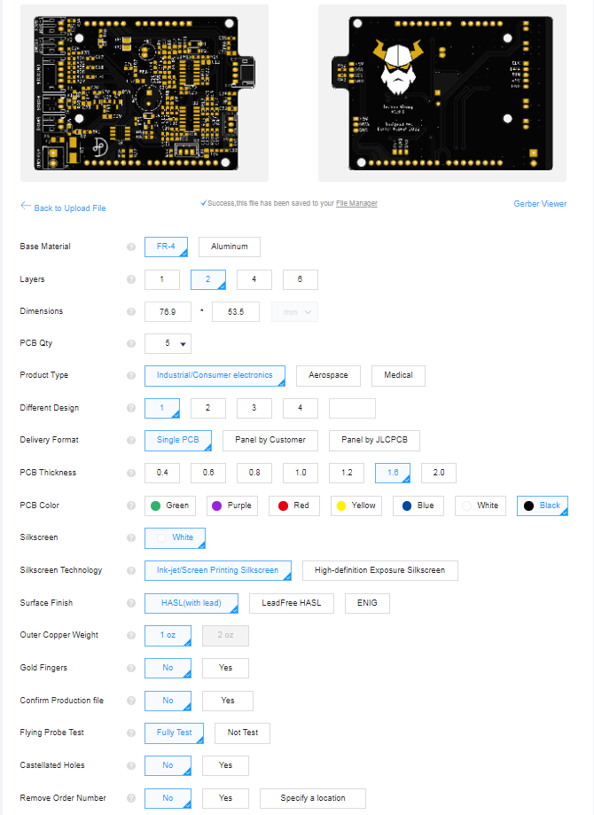
You also need some naked PCB panels, I highly recommend JLCPCB. It is cheap and fast. The quality for this price is very good, and the interface is simple. Just upload the gerber files and fill inthe settings as shown below:
The whole PCB is designed with KiCad and it has a very useful plugin called Interactive HTML BOM. This plugin generates a browser-based interactive tool, where you can find all the components needed for the board. Also, it shows where those components shall be placed on the PCB.
Of course, if you don't like the browser version of the BOM, you can open the whole project with KiCad.
This section explains the different modules and their job on the panel. You can skip this part if you are not interested in circuit design.
This part consists of seven amplifier stages:
This part generates exactly half of the supply voltage. The filters need a reference voltage between the power rails to swing the output voltage up and down. This is why we need a half-supply generator. Also, this means that the filter's output voltage is shifted to half supply instead of 0V.
This section is responsible to supply the circuits safely. It has a thermal fuse, a TVS diode, and polarity protection. I tried to make this as safe as possible.
The endstops are just simple switches, they have to be debounced. This simple part does this job.
The panel has a small buzzer. It is useful to create some interaction when you navigate the menu. This section consists of a transistor, that drives the buzzer, and some power filtering. The driver stage has a protection diode, so both electromechanical and piezoelectric buzzers can be used.
This is just a connector for the display cable with two pull-up resistors for the I2C signals. It also has some power filtering.
The circuit is the same as the buzzer driver. Its job is to drive the motor.
The circuit is the same as the buzzer driver. Its job is to turn on or off the humidifier module.
This contains two connectors for the two LED strips and some power filtering. It also has some series resistance, which is required to use the WS2812 and WS2813 chips properly.
The encoder is three switches, they have to be debounced. This section does this.
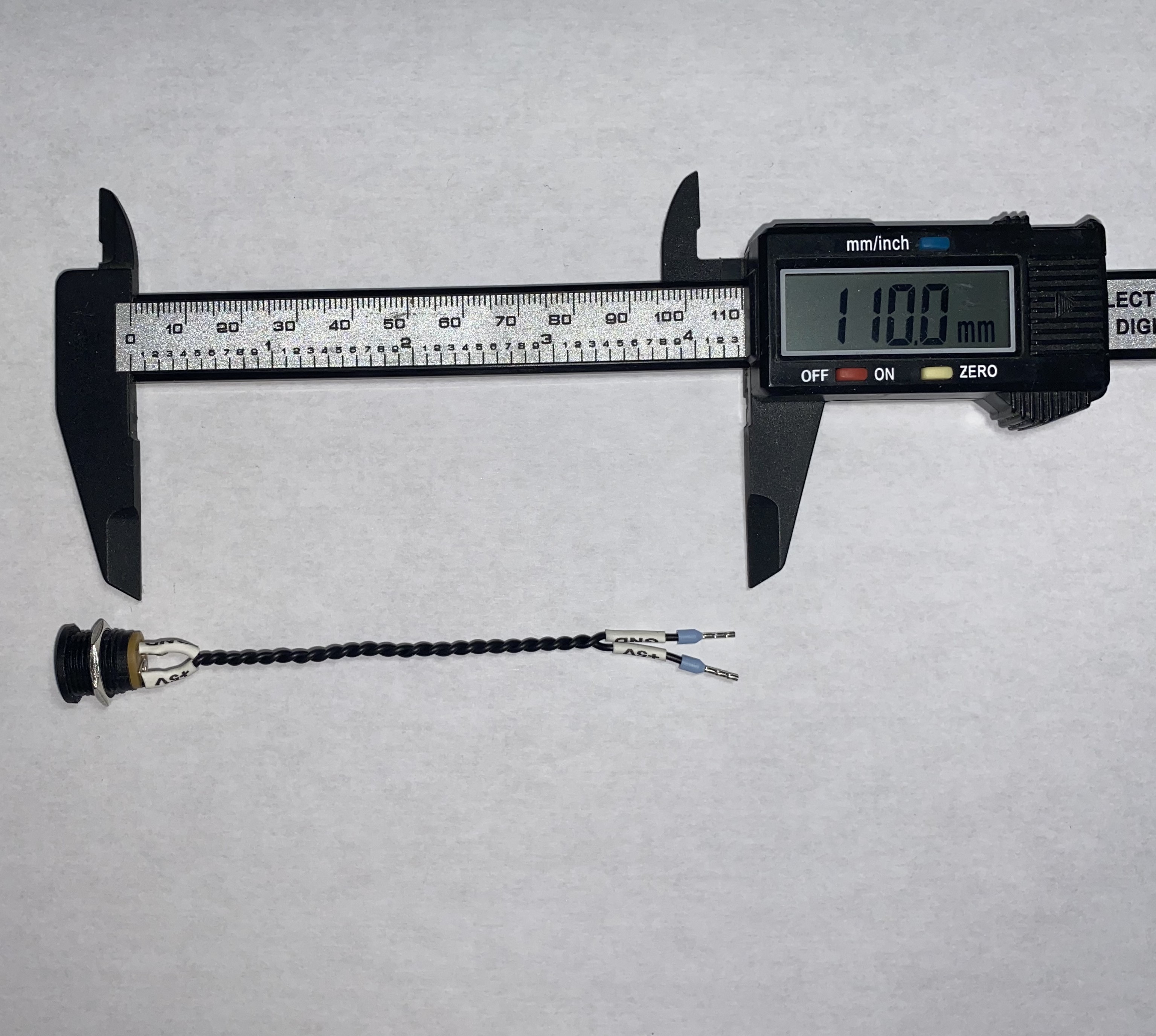
The cable length from the connector to the end sleeves is approximately 110mm, the cable is 0.22mm2 ( 24 AWG ), and the ends have cable end sleeves. The connector, that I used can be found here.
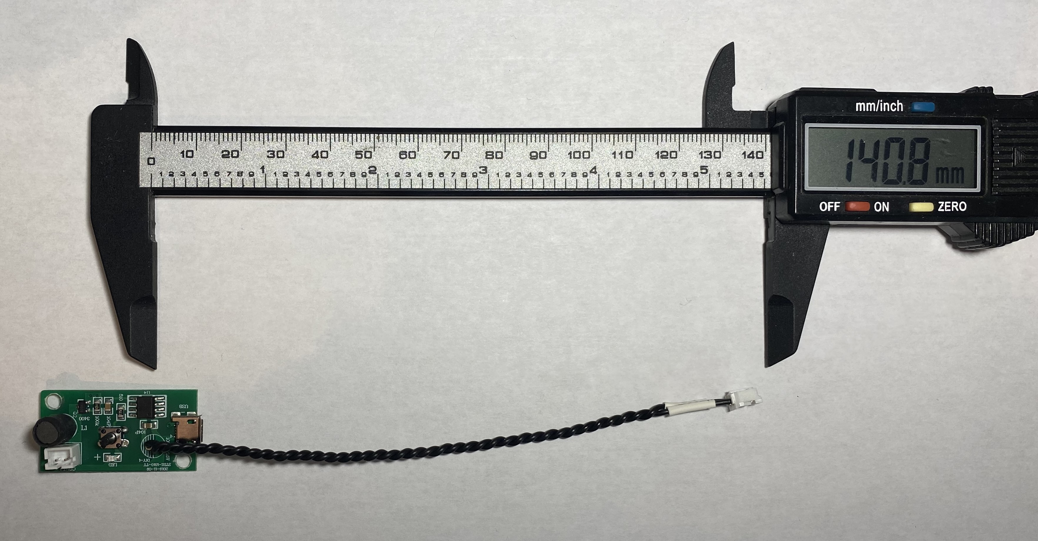
The cable length from the humidifier to the end connector is approximately 140mm, the cable is 0.22mm2 ( 24 AWG ), and the end has a PHR-2 JST connector. The connector, that I used can be found here. The crimping tool for the connector, that I used can be found here.
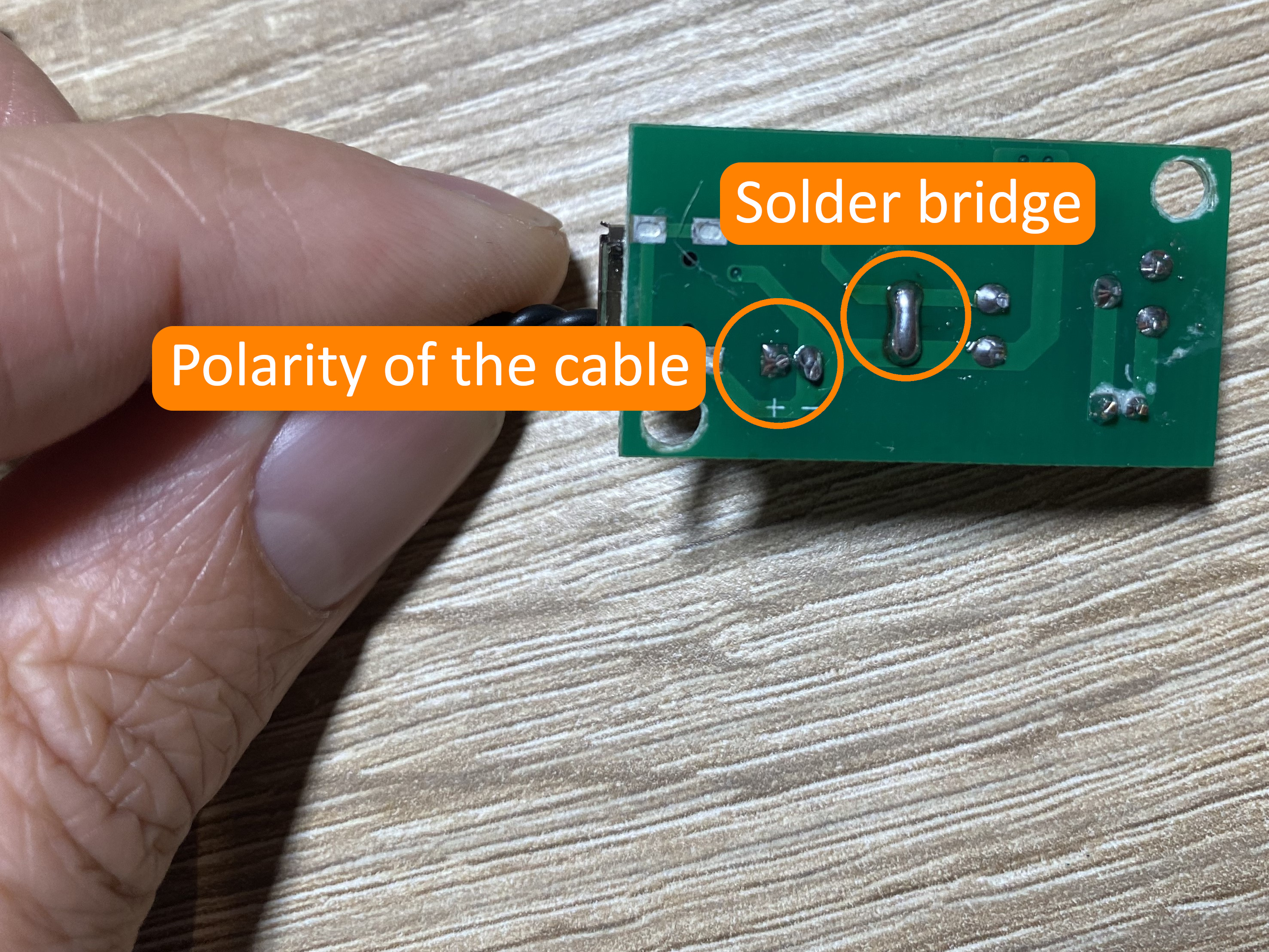
The polarity is marked at the back side of the humidifier board. Also, a little solder bridge has to be made to turn on the humidifier without a button press. The humidifier module, that I used can be found here.
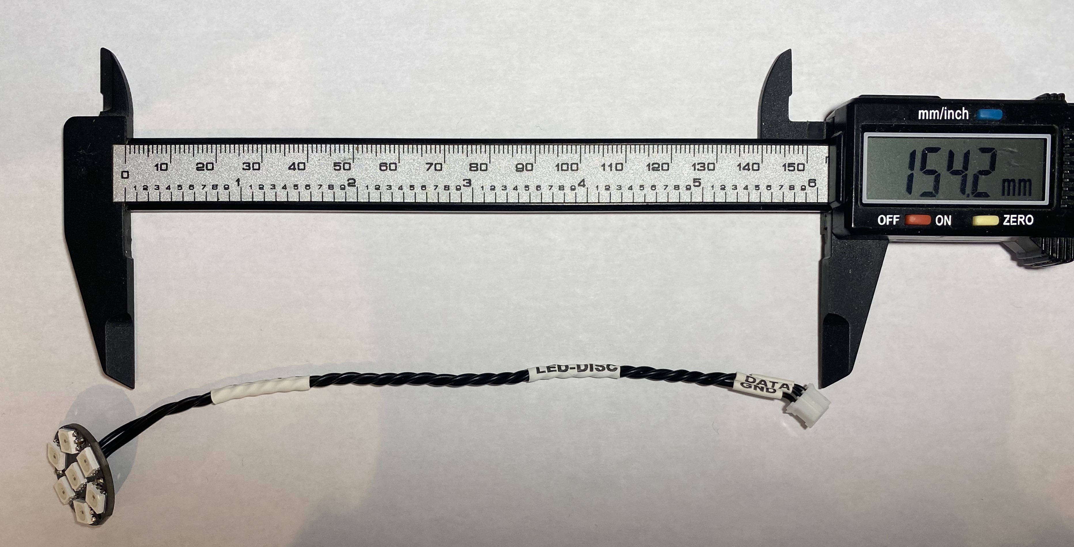
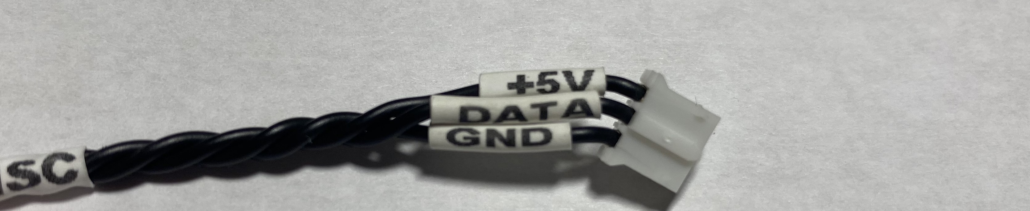
The cable length from the LED disc to the end connector is approximately 160mm, the cable is 0.22mm2 ( 24 AWG ), and the end has a PHR-3 JST connector. The connector, that I used can be found here. The crimping tool for the connector, that I used can be found here.
The LED disc, that I used can be found here.
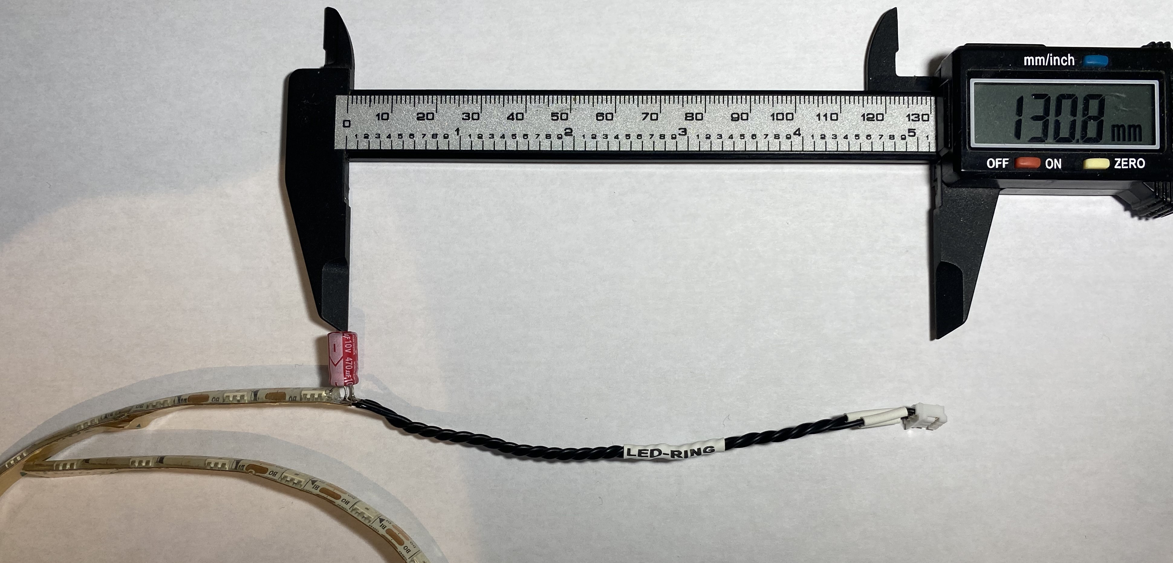

The cable length from the LED strip to the end connector is approximately 130mm, the cable is 0.22mm2 ( 24 AWG ), and the end has a PHR-3 JST connector. The connector, that I used can be found here. The Crimping tool for the connector, that I used can be found here.
LED strip, that I used can be found here.
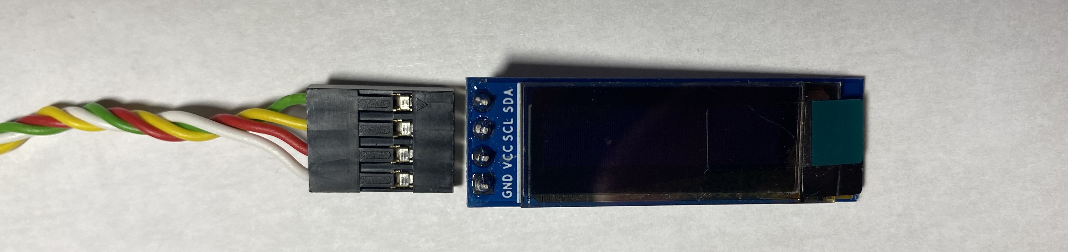
The cable length from the Oled display to the end connector is approximately 210mm, the cable is 0.22mm2 ( 24 AWG ), and the end has a PHR-4 JST connector. The connector, that I used can be found here. The display side of the cable also has a connector, it can be found here. The crimping tool for the connector, that I used can be found here.
The oled display module, that I used can be found here.
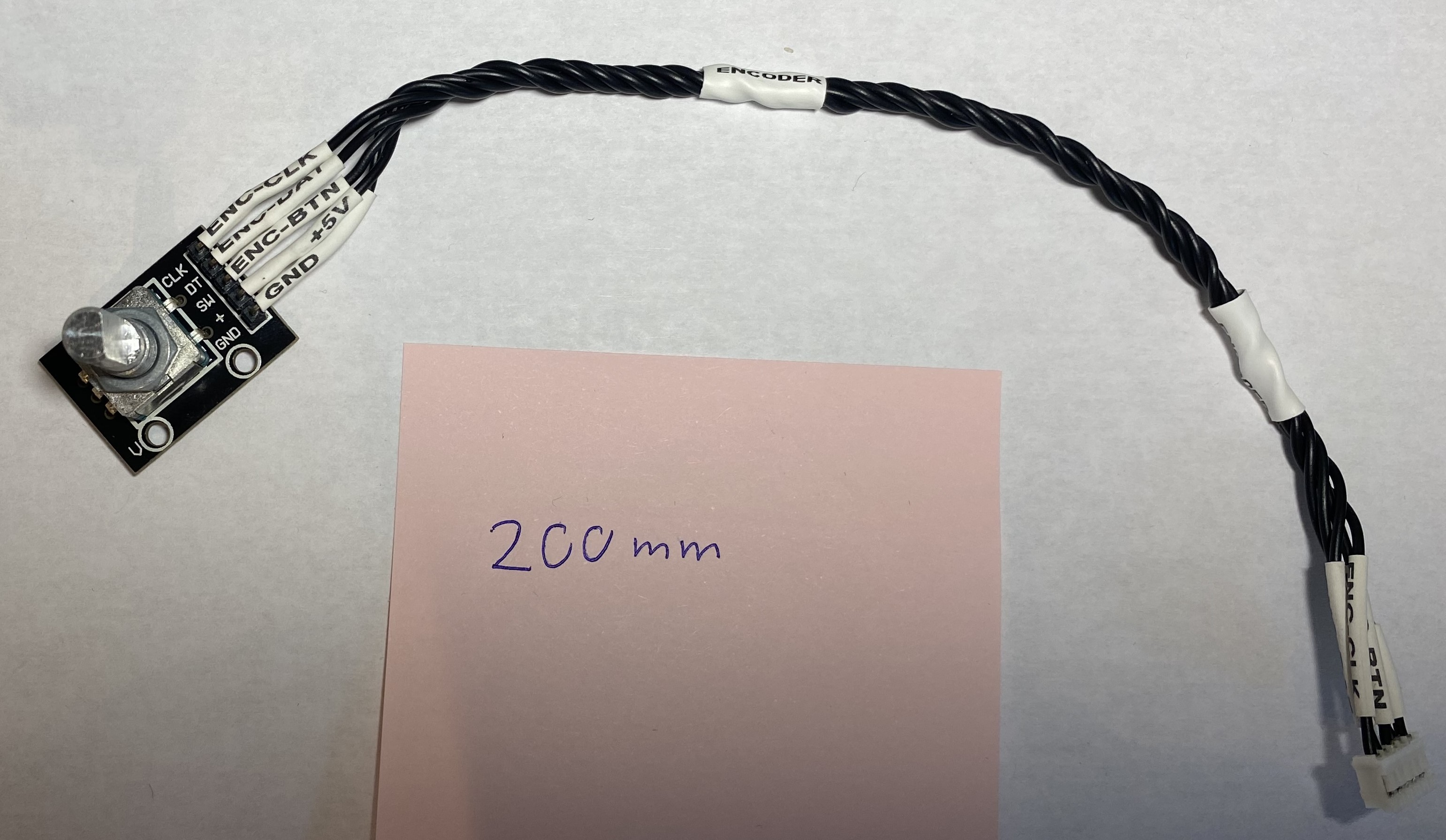
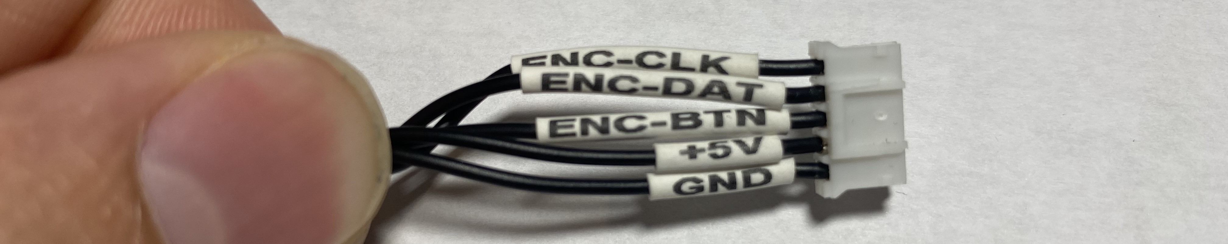
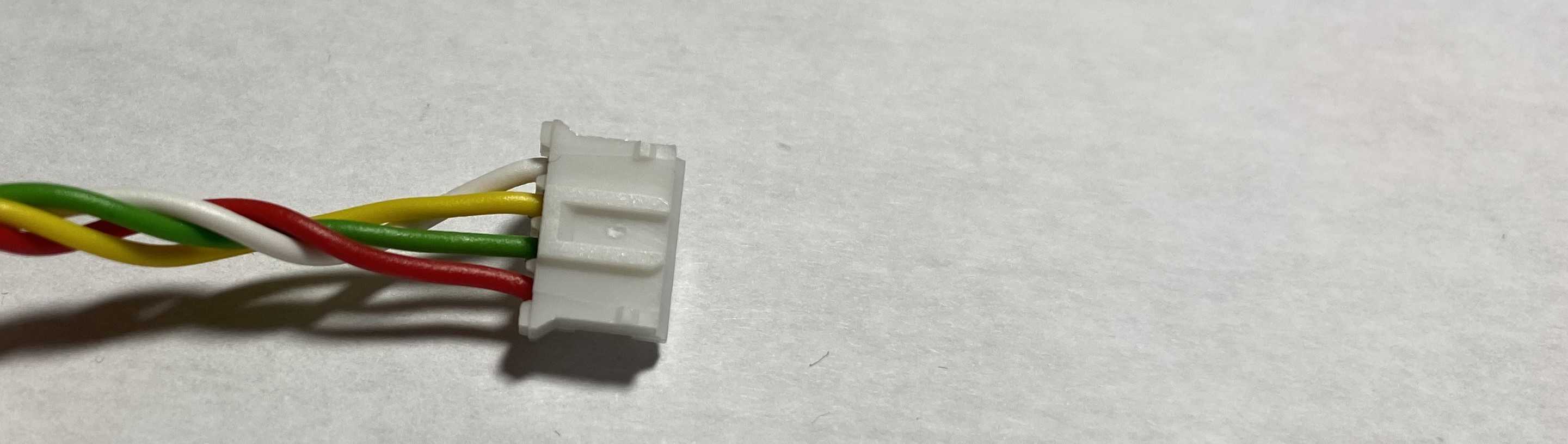
The cable length from the encoder to the end connector is approximately 200mm, the cable is 0.22mm2 ( 24 AWG ), and the end has a PHR-5 JST connector. The connector, that I used can be found here. The crimping tool for the connector, that I used can be found here.
The encoder module, that I used can be found here.
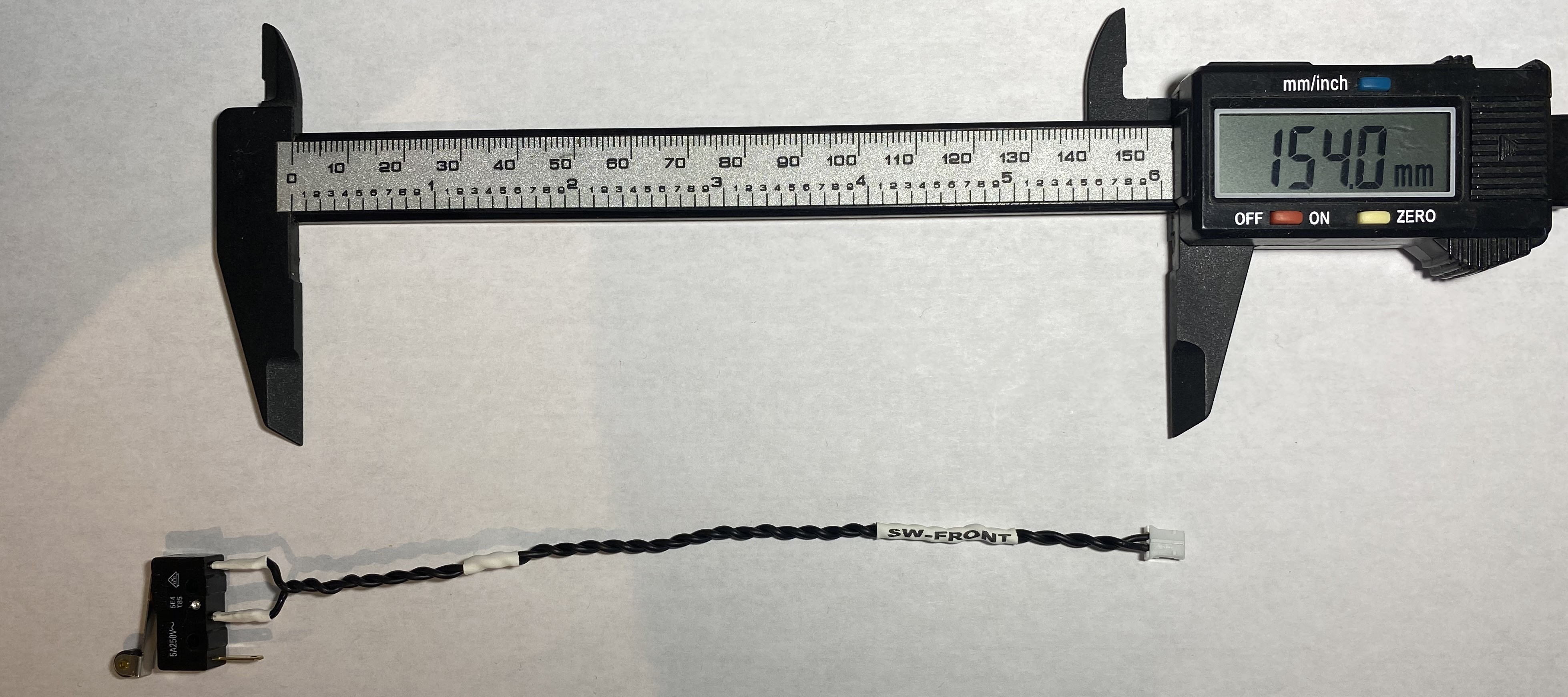
The cable length from the front endstop to the end connector is approximately 155mm, the cable is 0.22mm2 ( 24 AWG ), and the end has a PHR-2 JST connector. The connector, that I used can be found here. The crimping tool for the connector, that I used can be found here.
The endstop switch, that I used can be found here.
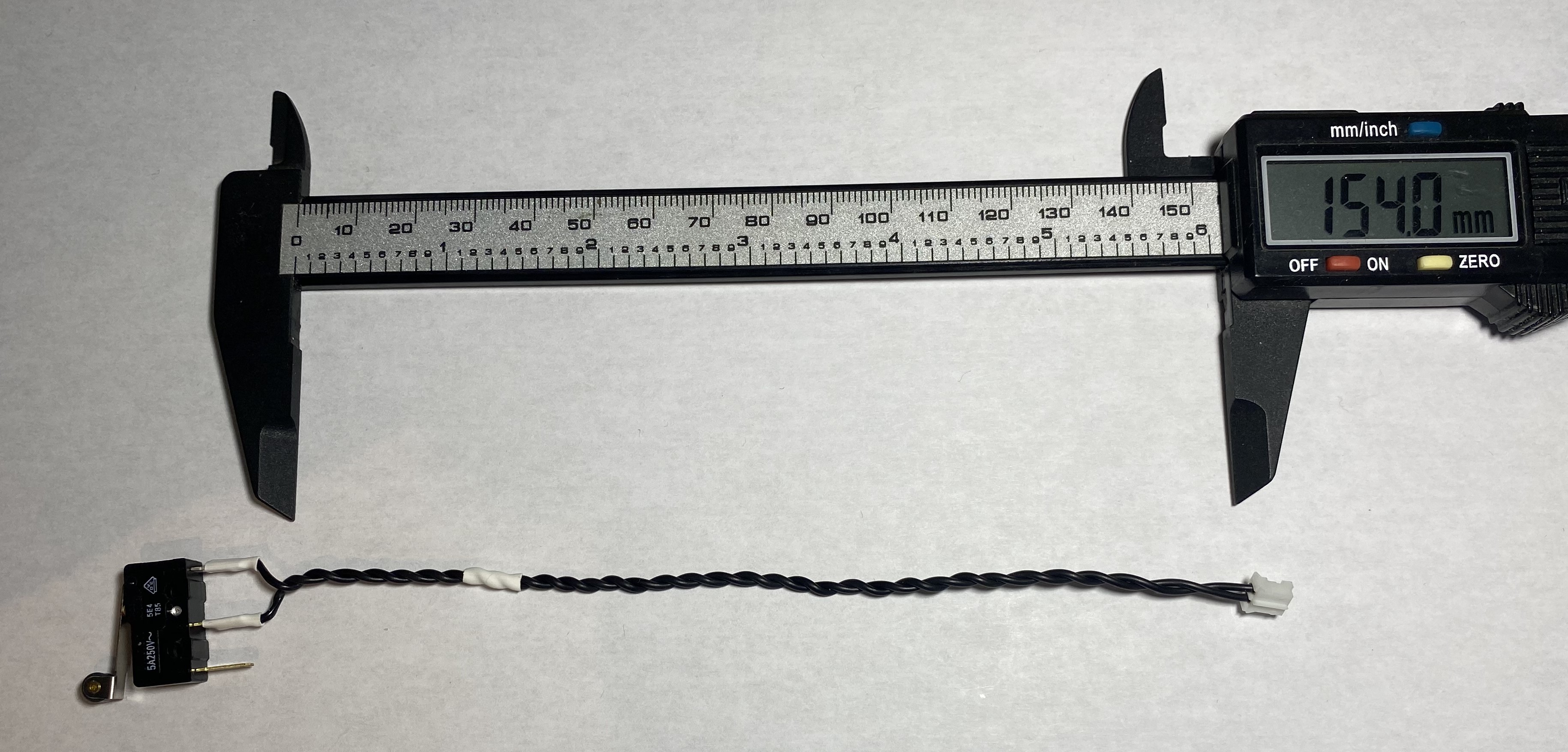
The cable length from the back endstop to the end connector is approximately 155mm, the cable is 0.22mm2 ( 24 AWG ), and the end has a PHR-2 JST connector. The connector, that I used can be found here. The crimping tool for the connector, that I used can be found here.
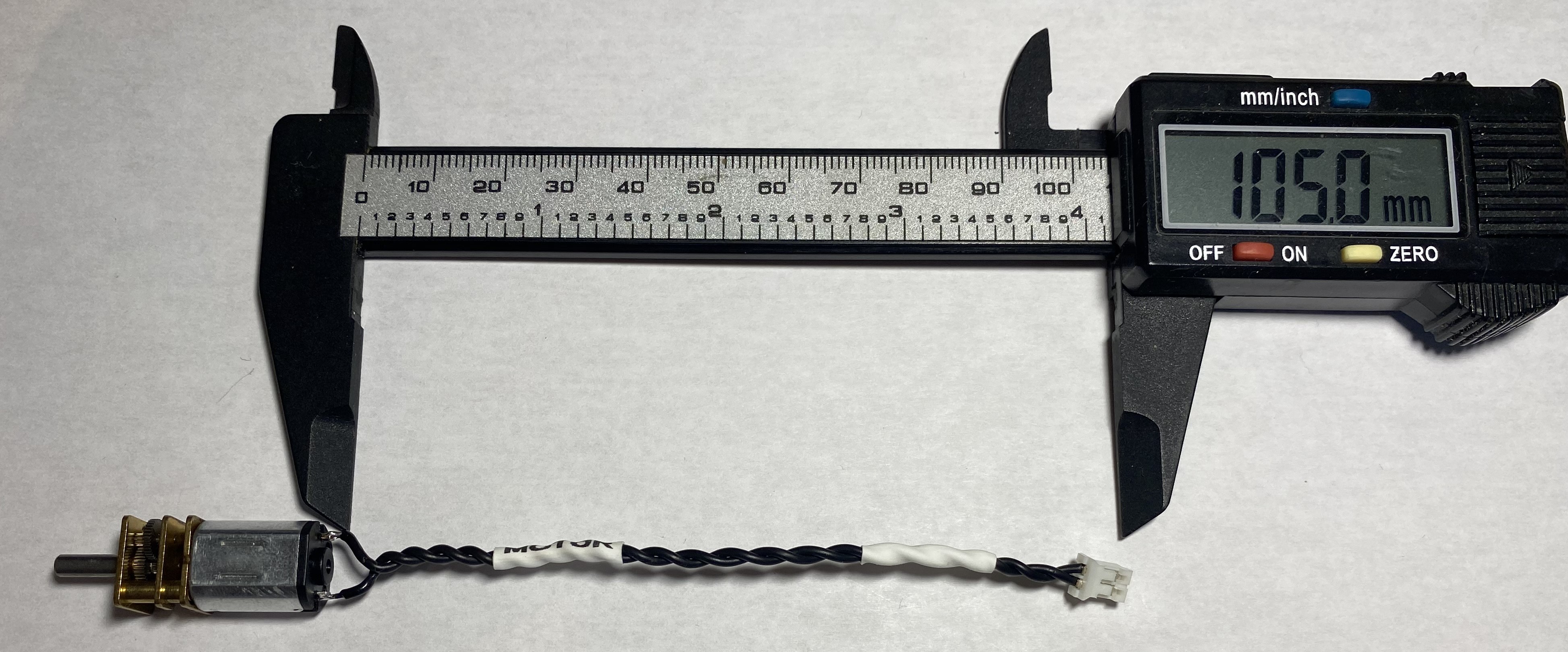
The cable length from the motor to the end connector is approximately 105mm, the cable is 0.22mm2 ( 24 AWG ), and the end has a PHR-2 JST connector. The connector, that I used can be found here. The crimping tool for the connector, that I used can be found here.
DC motor, that I used can be found here.
 on Sun Oct 16 2022
on Sun Oct 16 2022
on Sun Oct 16 2022